This thread has been locked.

If you have a related question, please click the "Ask a related question" button in the top right corner. The newly created question will be automatically linked to this question.

TPS40210-EP: The output voltage range of TPS40210-EP

Part Number: TPS40210-EP
Other Parts Discussed in Thread: TPS40210-Q1, TPS40210

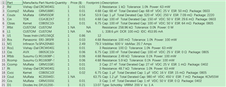
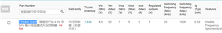
I find in the product filter page the output voltage range of TPS40210-EP is (7-9)V.  My application need a 105V output.

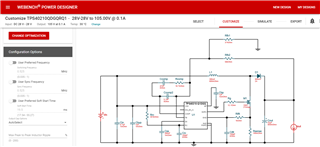
I make a design at Webench power design and find TPS40210-Q1 meets my application. I think TPS40210-EP meets too.

Please verify whether TPS40210-EP can achieve the 105V output voltage. Is the product filter list is incorrect?

when I use Webench I can find


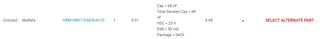
What is the meaning of Total Derated Cap? Is this mean I should plus 68nF in this example, 68+68=136nF, is this mean I'd better use a 136nF capacitor?

This is the first time I use webench, I feels good. Does this only can be used when designing power system? 

  • Hi Xiang,

    Thank you for your question.
    I am glad to hear, that Webench is a helpful tool for you.

    The TPS40210-EP has an input voltage range from 4.5V to 52V. The output voltage is only limited by the external components.
    The product details given in the filtering seem to be wrong, as neither the input, nor the output voltage range is stated correctly.
    If you are not sure, whether the device is suitable for your parameters, I recommend to always check the datasheet of the device. The specs given in the document are the ones that TI guarantees.
    www.ti.com/.../tps40210-ep

    In your case, the TPS40210 should work for your input and output values. However, you should check if the other components (inductor, MOSFET, diode, etc.) can withstand the 105V output voltage as well.

    Regarding the "derated cap" value, this is the final capacitance value. For example, if a capacitor looses some of its capacitance because of large heat, the total or "derated" value is lower than the original capacitance value. If both values are the same, it means there is no change in capacitance and the value stays 68nF for all operation situations.

    If you have further question, feel free to let me know.

    Best regards,
    Niklas

  • Thank you

    I still do not understand the "derated cap“, lets see the Bill of Material of a webench design.

    We can see from row 4, the "Total Derated Cap" (520nF) is smaller than "Cap" (1uF) , However in row 5 Total Derated Cap" (150nF) is smaller than "Cap" (100nF). Does the "cap" mean the original cap we should solder on the board and the "Total Derated Cap" mean the actual cap value when the board is in operation?  Can the actual cap become larger in some condition and become smaller in the other? 

  • Hi Xiang,

    Thanks for your feedback.
    I went deeper into the derated cap question and got additional information:
    First of all, the loss of capacitance is not only affected by temperature, but mostly by a DC biasing, especially for ceramic capacitors.
    For example, if you operate a ceramic cap with 100nF at a DC voltage of 50V, its capacitance can drop to 50nF.
    The exact capacitance value for a certain DC voltage can be seen in detail on the product page from the manufacturer, where TI takes the information from as well.
    More details about this topic are covered in this thread:
    https://e2e.ti.com/support/power-management-group/power-management/f/power-management-forum/714904/webench-tools-tps61085-meaning-of-derating

    However, the capacitance normally falls to a smaller value, which means the higher "derated capacitance" from row 5 of your image does not make sense.
    An explanation could be, that webench sees the quantity of 2 caps and calculated the derated value for both capacitors (with each one having an initial value of 100nF).
    For more investigation, I would recommend to check the product page for this capacitor from the manufacturer.

    Best regards,
    Niklas