Other Parts Discussed in Thread: BQ25710
Hi ,
may I know why Vout of charger is rise to 9V at first and then drop and eventually rise up to 12V
would you help elaborate this power sequence as detail as possible ?
thanks
Regards,
Fred
This thread has been locked.
If you have a related question, please click the "Ask a related question" button in the top right corner. The newly created question will be automatically linked to this question.
Hi, Fred,
Please provide schematic and register settings.
Regards,
Tiger
Hi Tiger,
upload schematic 8233.TI_Question.pdf
I think my question will be focus on why the Vout is 9V at the beginning when battery voltage is 9V for that moment and then drop,
and BTW there's no battery connected until red circle timepoint below.
Hi, Fred,
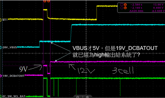
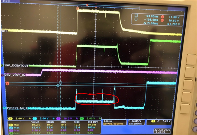
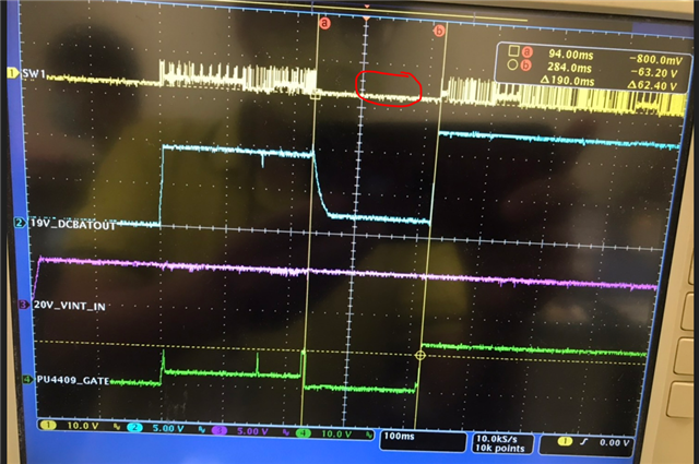
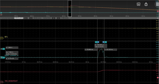
This is typical for a USB-C input. The PD controller decides the VBUS is either 5V or 20V. The charger finished startup in the first 200ms. The 9V is the battery voltage. The system rail follows the battery voltage from a to b time period, since it is connected by a body diode. When the system rail was raised to 12V by a command, the BATFET turns off when charging is inhibited, while turns on when charging is enabled.
Since the BQ25720 is a buck-boost battery charger, it operates from a wide input 3.5V to 26V. It can operate at 5V input.
Regards,
Tiger
Hi Tiger,
would you answer below two question with the below I2C log, customer is confused , thanks
and BTW, there's no battery during the whole time
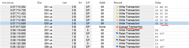
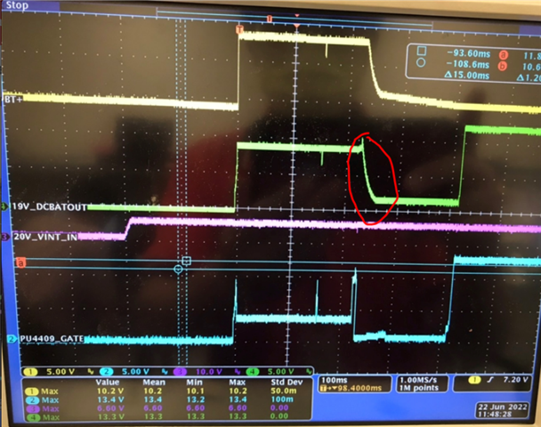
1. May I know which command cause the charger output voltage drop?
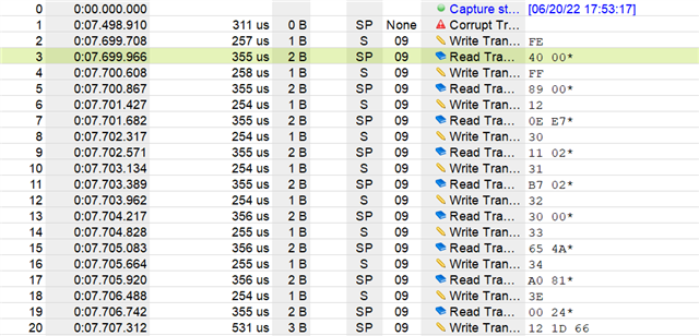
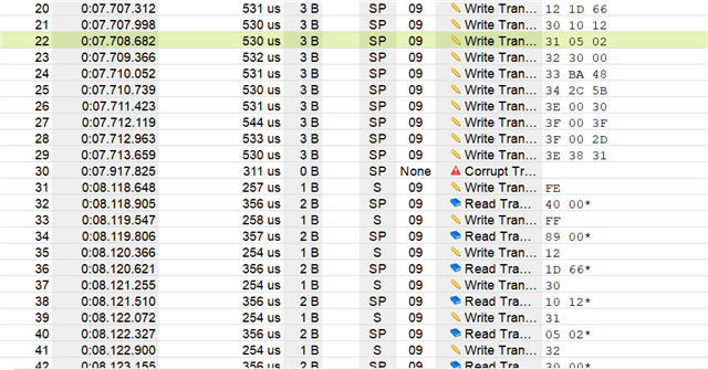
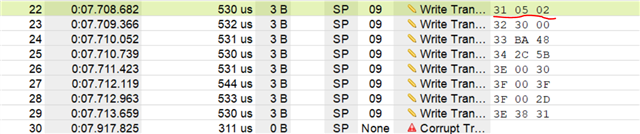
I saw a I2C "corrupt transaction" right after writing minimum system voltage to 12.544V ,
and customer said this sometimes occur sometime it doesn't.
what's the reason that cause this?
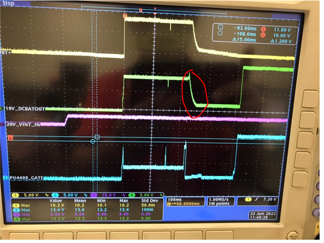
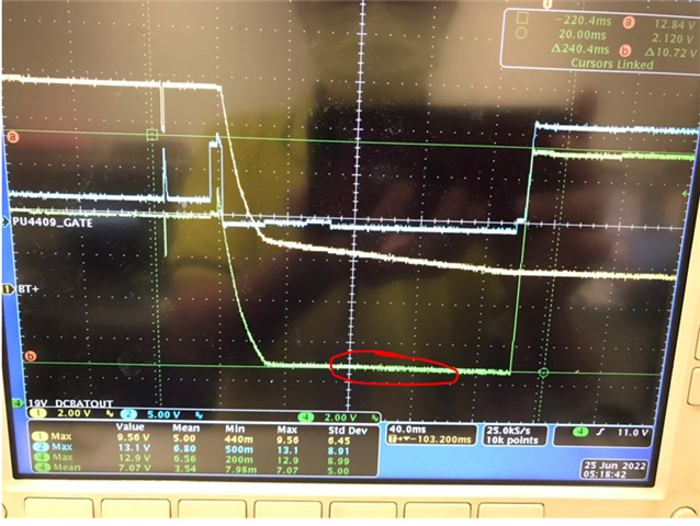
2. why the BATDRV at red circle is at 3.xV such a strange voltage, based on what I know it should be VSYS or VSYS-10 (which VSYS is around 9.216V that time)
Hi, Fred,
1. During startup, Please wait 200ms before configuring input current limit. Otherwise, the settings will be overwritten or be discarded. Not sure if this will cause corrupt transaction.
2. Could BATFET be in the linear region?
Regards,
Tiger
Hi Tiger,
not sure if you look into the log I upload
would you elaborate why the charger output voltage would drop if we set input current limit (3Fh) too early?
and I'm curious why I2C data failure like corrupt transaction would potentially affect buck-boost output ?
since I thought only minimum system voltage and charge voltage setting would change charger voltage.
BTW, like I said sometimes this voltage drop and corrupt contraction don't happen like below
please help, customer is kind of urgent, thanks.
The output drop is because there is no battery, otherwise the system rail will stay on. This has nothing to do with the I2C collapse.
Hi Tiger,
would you elaborate detail regarding why Vsys drop because of no battery like which signal is triggered ?
I thought output is not supposed to drop since we still have VBUS 5V supplying.
Vsys output drop to about 2.4V as below shown, and the SW1 is not switching at all at that time
please help since customer is urgent , this might affect business
Regards,
Fred
As you said, SW1 is not switching, there is no energy from the VBUS 5V. Since there is no battery, any system current will pull down the system rail.
Hi Tiger,
I don't think you got my point,
by VBUS I mean Vin=5V,
charger is supposed to function even without battery since we still have "Vin" adapter source.
Would you explain why charger stop switching for a moment?
OVP , OCP, inrush current , I2C setting failure?
again, customer is really urgent , thanks
Do you know the system load during startup?
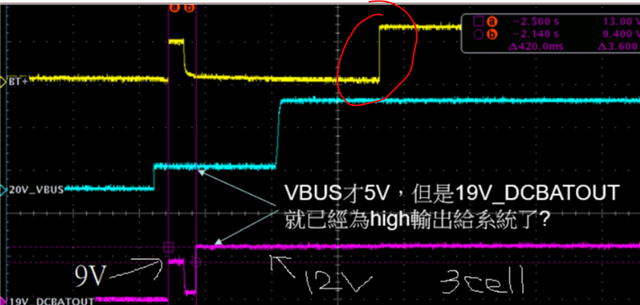
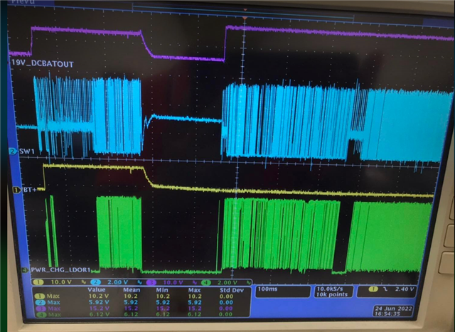
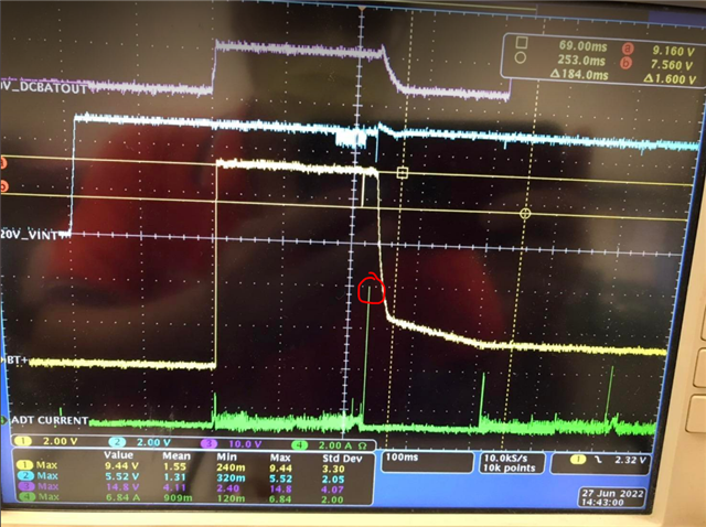
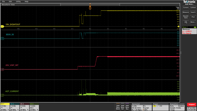
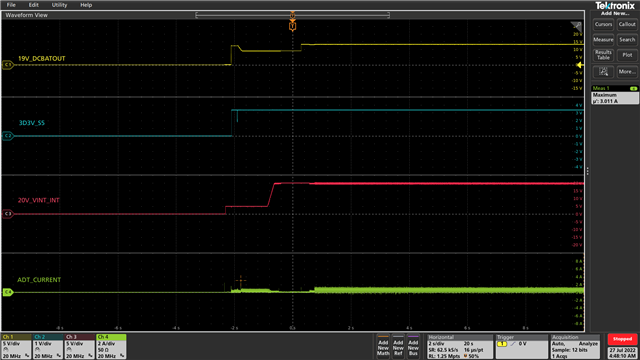
The charger startups okay after Vin=5V is applied. It startups to 9.2V min system voltage after 200ms. When the system draws more current, the system rail may not able to support the load, and runs into OCP protection. the switching will stop. This happens when battery is unavailable and Vin is low. When the adapter voltage increases to 20V, more energy is available to the system load, it starts to 12.5V successfully.
HI Tiger,
thanks for reply,
as you can see, there's a peak current at type-C adapter (can't measure charger input current), which is about 7.4A.
this peak current really looks like the root cause,
but ACX_OCP threshold is 15A (150mV/10mohm) or 28A, I don't think neither of these are triggered.
do you have any clue that can prove this is 100% OCP event?
BTW one thing I think you got wrong is that when the output is back to 12.5V, 20V_VINT_IN(Vin) is still 5V instead of 20V,
so I think this has nothing to do with low Vin
When the adapter current is 7.4A, the IINDPM is also activated. EXTLIM is set to 1.5A. Please work with the customer to reduce the peak current.
Hi Tiger ,
I am confused now ,
so you mean it's not OCP?
then would you explain why converter stop switching when reach input current limit?
IINDPM only decrease or stop charging current as far as i know.
Regards,
Fred
Hi Tiger,
1.Is there any 100% proof that OCP is triggered, after all we can't capture charger Iin
2. the input peak current only appear for a short period of time , but the charger stop switching for like 200ms long,
I wonder why?
please help answer above two question ,
thanks
Hi, Fred,
To confirm the fault signal, we need to check the register dump. Please send all the register settings.
Regards,
Tiger
HI Tiger,
upload register again, the PROCHOT is low , but it doesn't show PROCHOT register feedback
,I think they did something on EC setting, which will make us difficult to debug
Do you know how to open the TDC file? Maybe you can send me a screenshot of the register values.
This is the register log. We need to know the whole register values after the event.
Hi team,
update the latest situation,
quick recap, when remove battery, there's a drop when charger try to change minimum system voltage from 9.2 to 12.5V
However, we now discover if we set the default minimum system voltage to 12.28V by changing CELL_BATPRESZ.
the drop won't even occur.
below is original one
ch1 is charger Vsys
ch2 is the converter output right after charger
ch3 is the charger Vin (type-C)
ch4 input current of charger
and this is the one default is 12.28V
please help support why and how can we avoid this drop with default 9.2V, thanks
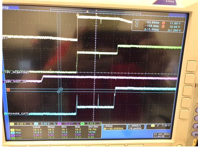
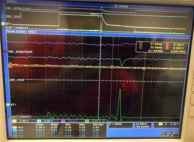
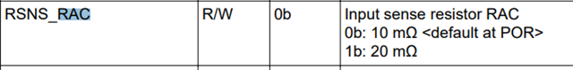
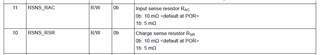
As you see on the waveform, the adapter current level is different. When min system is 9.2V, it draws 6~7A, resulting in system rail drop. When the min system is 12.3V, it draws less than 3A. The system can support. Suggest lowering the RAC current sense to beef up the current.
Hi Tiger,
what did you mean by " system can't support"?
if it's the input current limit,
theoretically the Vsys is supposed to back to 9.2V since the peak current only occur for a short period of time,
but instead it keep dropping even when there's no adapter current anymore,
do you know why?
RAC can't be smaller, It's already 10mohm .
The default input current limit is 3.25A. You only need 250us to trigger the ACOC fault. The charger also waits 250ms to restart. BQ25720 can support RAC 5-mohm.
Hi Tiger,
I got your point that you think it might be ACOC,
but as you know know ACOC is disabled by default
and I check the I2C log as you can see above, no sign of turning on ACOC in the 0x31,
how do you think?
Regards,
Fred
Hi, Fred,
Try above suggestions and provide the whole register dump if you can.
Regards,
Tiger
Hi Tiger,
it's hard to get register dump since it's at startup time,
BTW, sorry for confusing you but this case is BQ25710, so minimum RAC is 10mohm.
it it's not ACOC, then changing RAC is meaningless as well
Regards,
Fred
they keep encounter VSYS voltage drop about 200ms and back on again during 5V VBUS startup as you can see at the first picture,
BTW, this issue has taken so long and unresolved, I'll organize the material I got and set up a webex call with you ,
this way will be more efficient
I'll send you email later
thanks
Regards,
Fred