A related question is a question created from another question. When the related question is created, it will be automatically linked to the original question.
If you have a related question, please click the "Ask a related question" button in the top right corner. The newly created question will be automatically linked to this question.
Thanks for your patience. Please find the following comments.
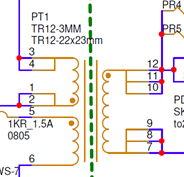
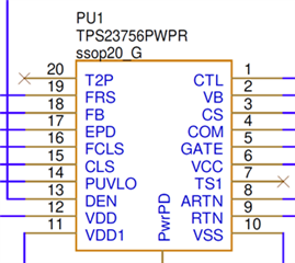
1.I saw you have multiple green components marked “NC”. Does that mean these components are not populated?
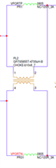
2.Could you send me the datasheet of this flyback transformer?
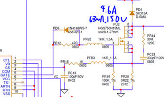
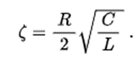
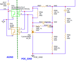
3.I have some concerns about the snubber circuit (PR44 and PC23) and current sensing with the primary switch. I would recommend you to leave these components unpopulated as a backup solution. Concerns: 1). The PU2 is rated 150-V, and the major energy stored in mutual inductance when PU2 turns off could be released at the SEC side and the PD4 side circuit, it may not result very large voltage overshoot at the PU2; 2). The snubber circuit may cause a higher current flow through current sensing resistor when PU2 turning off. This may cause some issues for current control; 3). The bead (PFB3) reduces the damping factor of the RLC series circuit, which may not be good for the CS pin.
4.A soft startup circuit (D10, R15 and C24) is recommended. Which could help to limit the duty cycle rising speed during turning on.
5.For the GAT2: you can tie the DT to VB to disable the GAT2
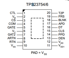
6.Please match the PIN configuration in the schematic with the datasheet.
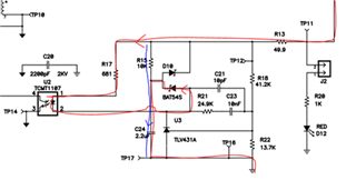
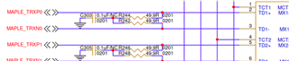
7.I just curious that these R (25 Ohm) and C (0.1 uF) filter create a low impedance path to the GND. Will that cause the data distortion? I am not good at the data field.
1. I saw you have multiple green components marked “NC”. Does that mean these components are not populated? The red part is using chock,green is "NC" not populated.
7.I just curious that these R (25 Ohm) and C (0.1 uF) filter create a low impedance path to the GND. Will that cause the data distortion? I am not good at the data field, ANS: Also reserved, no distortion in theory.
37.8 - 42 uH flyback inductance may easily result in discontinues current at light load and high current ripples. >100 uH and 4:1 turns ratio are recommended.