This thread has been locked.

If you have a related question, please click the "Ask a related question" button in the top right corner. The newly created question will be automatically linked to this question.

TPS51200: REFOUT max. capacitance

Part Number: TPS51200

Dear TI specialists,

as some of the users have asked in this forum, we haven encountered during the design with the TPS51200 a problem with the overshoot on the REFOUT line. 

Looking in the forums, we solved the issue by using a 4.7µF capacitor added to the line. As some smaller capacitors were already at the end of the line, we ended up with a capacitance of around 5.2µF.

As this solution solved the overshoot problem, it raised some concerns from our customer that increasing the capacitance might produce unexpected events that could affect the performance of the product, as in the datasheet is explicitly specified that the capacitance shall not exceed the 0.47µF. Therefore I have a few questions on these regards:

- What is the exact reason why this limit has been set?

- Will this limit be removed/adapted in the future versions of the datasheet?

- Is there any potential issue that might occur if a higher capacitance (>0.47µF and <10µF) is used?

Thank you very much in advance

Best Regards

  • Hello,

    REFOUT is a buffer. If the output capacitor is increased, it can cause low phase margin issue or instability.

    In what conditions the overshoot happens?

    Regards

  • Hello Mahmoud,

    the overshooting occurs in normal operations with a capacitance of <0.47µF.

    Following one of the comments from your colleagues in the forum (https://e2e.ti.com/support/power-management-group/power-management/f/power-management-forum/833149/tps51200-maximum-refout-capacitance), we increased the capacitance and the problem disappeared.

    However, the questions are not solved, as it is unclear why this happens, how much can we increase the capacitance and at which point the instability appears.

    Do you have any analysis that points out why the maximum output capacitance was set in the datasheet?

    Thanks

    Regards

  • Hello,

    The root cause of the overshoot is the stray inductance from device pin to output capacitor. When REFIN is below 390mV, REFOUT and VO are close to 0V. When REFIN is above 390mV, the output sources large current so REFOUT and VO reach REFIN quickly. The large current stored in the stray inductance causes the overshoot. Minimizing the stray inductance will reduce the overshoot.

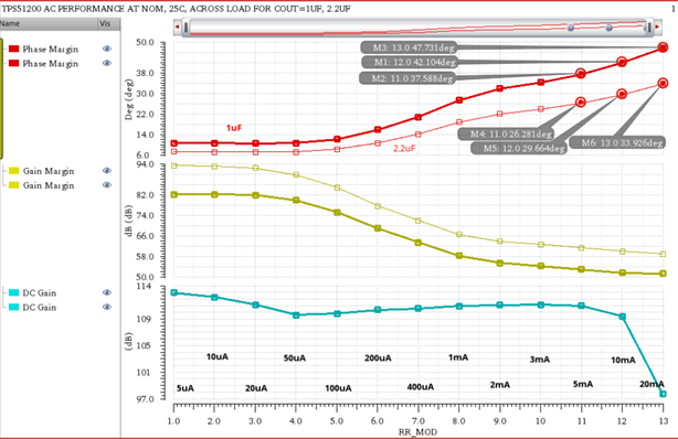
    Simulation data shows phase margin, at 10mA, is 42 degrees with 1uF and 30 degrees with 2.2uF. There is no data available with larger capacitance. 

    The capacitance of 0.47uF in the datasheet is based on higher than 45 degrees phase margin and very low stray inductance.

    As stated in the previous forum, the key is to solder the output cap very close to device pin or have a small resistor in series with large output cap. For example 10uF and 1 Ohm in series.

    Please close thread as resolved if your question is answered and let me know for further question.

    Regards

  • Hello Mahmoud,

    I talked to our customer, and we still have some doubts about the instability of the REFOUT output. 

    As you refer, increasing the capacitance reduces the phase marging, and therefore this can derive into instability. However, several threads in the forum refer to have increased the capacitance without adding further resistors and not having shown issues. I guess this is also depending on the load that is being connected.

    Do you have measurements of the stability and the phase margin with reference to the load or the capacitance? 

    Thank you

    Regards

  • Hello, here is the available data:

    Regards

  • Hello Mahmoud,

    sorry, that it took so long for the reply, we were discussing the topic with the customer the last weeks.

    Regarding the measurements, we have been trying with several capacities and load currents during some experiments, and we have not found any instability. Using the 1 ohm resistor in series with the capacitor helps to reduce the overshooting even more.

    Would it be from your perspective also possible to use the 1 ohm resistor in series with lower capacitances (like the ones recommended)? With that circuitry, we could keep the capacitance low and reduce the overshooting.

    Thank you very much in advance.

    Regards

  • Hello Leon,

    Yes the series resistor adds a zero to the loop and helps stabilizing it. Please let me know for further support.

    Regards

  • Hello Mahmoud,

    ok, thank you very much.

    Regards.