This thread has been locked.
If you have a related question, please click the "Ask a related question" button in the top right corner. The newly created question will be automatically linked to this question.
Hi all,
I have asked a question a while ago and replied to it as resolved, but upon further testing I have noticed that it wasn't resolved completely. I have replied with a follow up question to the same post, but I am not sure if it will be noticed since it is marked as resolved, therefore I have opened a new thread. If the moderators think that this is unnecessary, then this thread may be removed. Link to previous thread to see the full explanation: BQ76200: Slow turn off curve - Power management forum - Power management - TI E2E support forums
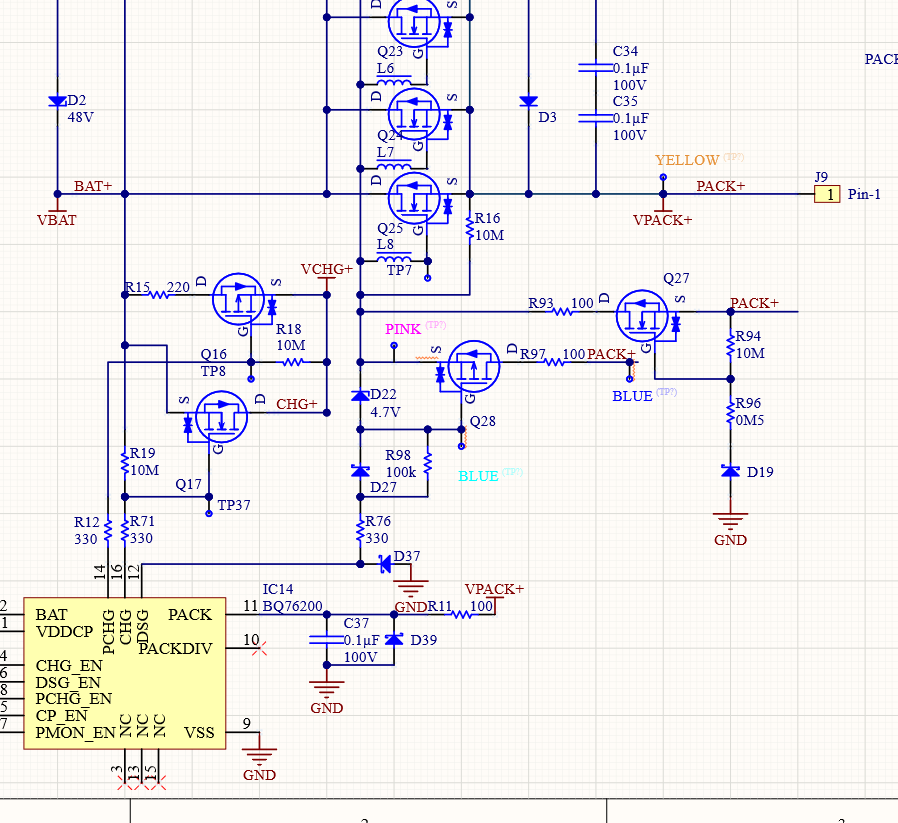
I have tried this solution (circuits around Q28):
With mixed success.
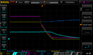
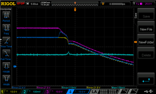
Initially when i turn this on, then Pack+ goes up, but when i turn off Pack+,then Pack+ and DSG (BQ76200) both go to Bat+.
When i remove Q27 (which is there for negative voltage protection), then it can turn off. The circuit for Q27 is based upon this application note:
(see figure 4)
The measurements points are indicated in the schematic.
The inital part of the turn-off curve is already better. (there is only a load of 2kohm attached to it for testing purposes.)
The power mosfets = NVMFS6H824NL
Q28 = DMG1013UW-7
Q27 = BSS123IXTSA1
It seems that when i am using Q27 that there is somekind of feedbackloop active. Can you see what I am missing here?
Best regards,
Jan
Hello Jan,
I don't see anything wrong with the circuit. The only thing is that we usually add a Zener between the gate-source of the reverse-charge FET (Q27) to protect it from exceeding ABS max. Additionally, the Q27 circuitry should be referenced to PACK-, not to VSS/GND. This is what we've done in our latest devices. Is there a way to modify the circuit to test by adding these two things?
The app note you listed also show some other considerations for reverse-charger circuitry when having higher voltage (>18-V) systems. Have you considered these?
So the turn-off circuit works when the Q27 FET is removed? It is rather strange that this circuit would affect Q28.
Best Regards,
Luis Hernandez Salomon
Hello Luis,
The missing zener is for limitting the gate voltage i assume?
The issue around Q27 seems to be resolved (a poor connection i believe).
I have done some more powertesting regarding the turn-off.
Dark Blue = Bat+
Light Blue = Vsense (100A)
Purple/Pink = Pink in the schematic (Source of Q28)
Yellow = Pack+
Result: the very first 10µs seam to be good, but then it looks like if Q28 turns off.
I have done a measurement to confirm this:
Dark Blue = Drain of Q28 (between resistor and mosfet)
Result: You can see that it starts to conduct, but it seems that it stops conducting when it reaches the level of Pack+.
Dark Blue = Anode of D27:
Result: You can see that the drive signal coming from the BQ76200 drops quickly which makes it possible to enable Q28. But after Q28 stops conducting, then the turn off continous to slow, nearly 150µs.
I thought that adding this circuit would decrease the turn-off time. But as you can see the puple signal remains a couple of volts higher than Vpack+ causing the mosfets to keep conducting.
Do you have any idea on how i can tackle this issue?
Best regards,
Jan
Hello Jan,
It is not apparently clear why the Q28 FET does not remain ON. Something to note is that we have not tested such circuit on this device and the switching architecture is somewhat different than that of the BQ76952. I assumed it would still work, so I am not sure why it seems that Q28 stops conducting.
Was there any difference if Q27 was removed?
Could you take a oscilloscope shot of the source-gate of Q28 and the gate of the DSG FETs?
Best Regards,
Luis Hernandez Salomon