hi the team,
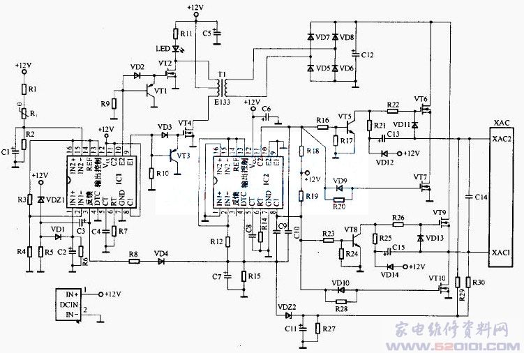
We have used lines like the following,
Its IC2 PIN4 DTC and PIN8 C1, PIN9 C2 are connected with capacitors(C9,C10),
We don't know why the capacitor is connected like this?

This thread has been locked.
If you have a related question, please click the "Ask a related question" button in the top right corner. The newly created question will be automatically linked to this question.
hi the team,
We have used lines like the following,
Its IC2 PIN4 DTC and PIN8 C1, PIN9 C2 are connected with capacitors(C9,C10),
We don't know why the capacitor is connected like this?

Jacky,
I'm not sure whyC9 and C10 are connected into the DTC? This makes no sense since the DTC is a DC signal capacitively "coupled" through C9 and C10? If you have waveforms to share, that would help?
Regards,
Steve M
hi Steven,
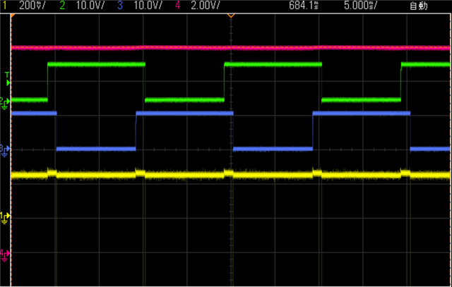
The waveform look like this,
C1(Green)/C2(Blue)/DTC(yellow),
I think it is Prevent out of control when C1 and C2 open at the same time,
How about you think?

Jacky
Thanks for sharing the waveforms. Looks good and I agree.
Regards,
Steve
HI Steven,
I have received one abnormal TL494 PCBA,
and I changing it to a MLCC capacitor,
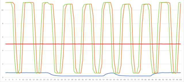
then C1, C2 singal look like good,
but the DTC is not very stable,
what will affect the DTC?
c1 : orange / c2 : green / DTC : Blue /Vref : red

Jacky
The DTC is a comparator input and is high impedance (<10 μA). I can't think of anything that would result in the waveform you are showing. My suggestions for debug would be:
Regards,
Steve M
hi steven,
we have try the high tempture test,
1.Look like the C1,C2 Switch to effect the output Freq (24.56~100HZ),at original tantalum

2.we are change tantalum to MLCC => look like is ok
3.then we are change MLCC to Origial tantalum => the C1,C2 Signal look like better then Origial tantalum,output Freq(39.5~49.23HZ)

I don't know what could be causing the difference(when Origial tantalum => MLCC => Origial tantalum )?
item 5 What effect does leakage current?Freq?
Jacky,
I'm not sure? Is this happening on one board only, or can you verify this to be the case on multiple boards?
Steve
hi steve,
There are currently 3 pieces of this phenomenon,
I tried to touch the tantalum on yesterday, and found that the output frequency will change to 90hz
Jacky,
Based on what you are observing, all signs are pointing to sensitivity/differences between capacitor types. From here, I would suggest that you stick with the ceramic X7R which I recommended and seems to be giving you the desired performance or else you will need to deep dive into the electrical performance differences between these two capacitor types. You need to decide if this is worth the effort based on the time spent and how valuable the information is that comes back as a result of your effort? A deep dive comparison could include measuring the impedance characteristics of each on a network analyzer, comparing temperature and tolerance variation (data sheets), comparing measured ESR, SRF, capacitor value vs DC bias effect and leakage current between each...these are just a few of the most important differentiating parameters that come to mind.
Regards,
Steve M