This thread has been locked.

If you have a related question, please click the "Ask a related question" button in the top right corner. The newly created question will be automatically linked to this question.

TPS65217: PMIC loses 3.3V on LDO3 and other outputs

Part Number: TPS65217
Other Parts Discussed in Thread: AM3354, ,

Hello,

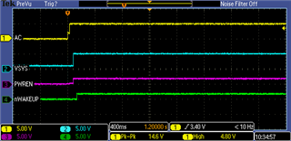
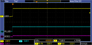
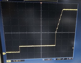
We are using the TPS65217B with a Sitara micro (AM3354), and occasionally we get boards that no longer power up. We use a dedicated 5V supply to power the PMIC through the AC pin, which seems to be solid. We probed the PWR_EN and nWAKEUP pins, and it appears that PWR_EN is held to about 1.8V, then eventually shuts off. WAKEUP goes high (5V) for about 75mS, then turns off.  Is this a sign that the PMIC has failed, or the micro has failed?
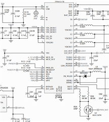
Design -

Thanks,

Doug Franck

EE

  • Hi,

    Thank You for using E2E! The Apps engineer who is currently supporting the TPS65217 PMIC is out of office, returning next Monday 05/22/23. Please expect an update on this by 05/24/23. Thank You for your patience. 

    Thanks,

    Brenda

  • Hi Doug,

    Can you provide a PDF of the schematic that shows the full design? The edges of the picture you posted are cut off and I would like to see the full build if possible. I can set up a direct message if you need to send the schematic files privately.

    Also, can you share a scope capture with us? We should compare the working board waveforms to the behavior you are seeing. A capture showing VAC (input power), VSYS, PWR_EN, and nWAKEUP would be a good start. The general power-up process involves applying proper input power to AC, nWAKEUP should be pulled low for 5 seconds once the PMIC detects the AC input. In this 5-second window, PWR_EN needs to be pulled high to start the full power-up sequence.

    Regards,

    James

  • Hi James, what's the best way to send you the schematic?

    Thanks,

    Doug

  • Hi Doug,

    You can add the schematic PDF as an attachment in your next reply or if you need to send it via private message I can set that up.

    Regards,

    James

  • Hi Doug,

    1) Thank you for providing the PDF. 

    It looks like you have all the necessary components but double check that all output capacitance requirements are met according to this TPS65217x Schematic Checklist (Rev. C)These capacitors should be as close to the output as possible. We can refer back to the schematic based on our future findings.

    2) Can you also share a full register dump before and after the PMIC power up fails?

    3) If you provide the following scope captures, I can look for a fault condition in the power up sequence:

    • CH1: VAC, CH2: VSYS, CH3: PWR_EN, CH4: nWAKEUP
      • trigger off of VAC and show the sequence after PWR_EN is pulled high during the nWAKEUP 5 second window

    • CH1: VSYS, CH2: VLDO1, CH3: DCDC1, CH4: LDO2
      • trigger off of VSYS and show the power up of each output rail

    • CH1: LDO2, CH2: LDO3, CH3: LDO4, CH4: DCDC2 or DCDC3
      • trigger off of LDO2 and show the rest of the power up sequence. Also check PGOOD voltage to see if PGOOD signal is pulled high before the shutdown or if PGOOD remains low.

    The goal here is to find out where the sequence fails or what specific event causes the shutdown.

    Regards,

    James

  • James, here is an example of one of the outputs not responding as expected. Our backlighting for the LCD is supposed to jump to 14V. We have quiote a few boards where this isn't happening. Does this seem like the chip has been overstressed and has gone bad?

  • Hi Doug,

    The L4 and FB_WLED pins on the TPS65217B are rated for up to 44V absolute max. The recommended Vout max is 32V (overvoltage protection starts at 38V typically).

    I did some tests on our TPS65217DEVM and confirmed that the FB_WLED pin voltage should sit at around 5V when the LED current sink is disabled (REG07[3] = 0b). When the sink is enabled (REG07[3] = 1b), the voltage rises above 30V (See the attached document below for the EVM schematic).

    In your last scope capture, a voltage spike does not occur on the FB_WLED pin and the voltage only rises to 5V. It doesn't look like the current sink is being activated in this situation. On the other scope capture, after the voltage spikes up above 30V the output stabilizes at 14V which would indicate the LED current sink is at least being enabled.

    • What is the peak voltage of that spike in the second to last capture?
    • Can you check REG07 bit 3 in both situations to see if ISINK_EN is either HIGH or LOW?
    • One thing you might want to try is connecting the ISET1/2 pin resistors directly to GND, without the FET connection. In our recommended schematics we don't include the FET. I don't know for certain that the FET is causing an issue but it might be something to try.

    Page 4 of this document, shows a schematic of the EVM I am using for context.

    Below is a scope capture I took of the FB_WLED pin voltage. You can see the 5V point before I enable the LED current and the voltage rises to ~31V after I enable the LEDs.

    Also, here is a picture from the datasheet showing REG07 default settings at power up. The ISINK_EN bit is 0b by default so there my be something going on with your enable process.

    Regards,

    James

  • Hi Doug,

    Just wanted to add a quick note. The spike on the FB_WLED pin and the 14V resting point may not guarantee that the ISINK is being enabled. If the REG07 bit 3 is set to 0b but you are still seeing a voltage rise on FB_WLED, it might be coming from the LCD screen and not the actual boost converter block inside the PMIC. This is just a theory since I don't know how the LCD you are using works.

    Regards,

    James

  • James,

    Unfortunately, I don't have access to the PMIC registers. I tried shorting out the ISET1/2 resistors to GND, but saw no change. The spike on FB_WLED is about 39V (on the 1 board I tested). We build and ship about 3000 of these boards a week, and get back 1 or 2 a month with this issue. Do you think we're exceeding the limit on FB_WLED on certain boards?

    Thanks,

    Doug

  • Hi Doug,

    Considering that the overvoltage threshold can be as low as 37V (38V typical and 39V max according to the datasheet), I would recommend trying to rectify this spike so you don't hit the fault threshold. That being said, from your scope captures, it doesn't look like the power rails are failing when the spike hits.

    I don't think the overvoltage can be triggered when the WLED internal block is disabled but there's nothing in the datasheet to confirm this. The spike is strange but I'm not certain that it relates to your original shutdown issue.

    Regards,

    James

  • Thank you, James. I'll recommend a design change.

    Doug Franck