This thread has been locked.

If you have a related question, please click the "Ask a related question" button in the top right corner. The newly created question will be automatically linked to this question.

LM5149-Q1: LM5149-Q1 output voltage question

Part Number: LM5149-Q1

Hi Teams,

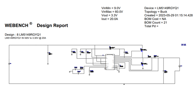
I'm setting LM5149-Q1 Vout: 3.3V、Iout: 15A、Ambient Temp: 85°C,when system Vin:40V to 3V to 40V,3V 10mS, rise time and fall time 0.1 mS

Q1: Output voltage figure

Q2: If have pulse how to avoid it

Thank you.

  • Hi Victor,

    If you can fill out this spreadsheet with your design parameters and reattach, it can help with an example schematic. Let me know if you have further issues.

    Regards,

    Henry

    6685.LM5149-LM25149 Quickstart Calculator_rev3.xlsm

  • Hi Henry,

    I'm setting as figure, but M1 and M2 need 160V, please help check this design, and have any suggest part for M1 and M2, Thank you.

  • Hi, Henry

    as Victor report by WEBENCH Designer LM5149-Q1 and we find High/Low side MOSFET is 160V, Could change 80v or 100v MOSFET?

    Condition:

    Vin=9V to 60V

    Vout=3.3V

    Iout=20A

    Ambient Teamp: 85 deg

    if any, Please advise me.

    Thanks,

    Best regards,

    Lawrenec

  • Hi Lawrence,

    Thanks for your patience. For the MOSFET I do believe that WEBENCH is on the conservative side since the VDS choice is dependent on VIN and SW node ringing. If there is too much SW node ringing the voltage may exceed breakdown voltage of the power MOSFET. This ringing is dependent on how well you can design the layout, and placing a snubber or using gate/bootstrap resistors to attenuate the ringing. Therefore, if you can control the ringing under 100V, the FET should survive.

    The applications section 9.1.1.4 of the datasheet shows the main considerations of choosing a power FET for this device. Once you have selected your device, the design calculator attached also has a FET input parameter section that can determine efficiency with the FET. Please reattach once you've filled it out.

    For the schematic I advise you should link the WEBENCH design or upload a higher resolution schematic image, so I can best advise your situation. I cannot see the component values.

    Regards,

    Henry

    5148.LM5149-LM25149 Quickstart Calculator_rev3.xlsm

  • Hi Henry:

       This is FAE Roy. currently our customer consider design LM5149-Q1 for the 24V car battery for automotive support cold crank requirement. 

    The input cold crank input voltage variation from 40V drop to 3V with 10mS then back to 40V. customer want to know whether the output voltage of LM5149-Q1 will have overshoot problem under the condition of input voltage drop to 3V with Full loading condition(customer mentions other competitor will have overshoot when Vin drop to 3V with Iout =full loading)

    I have shown datasheet Figure 9-35 Cold crank response to Vin=4V, but Iout just only 1A load not full load conditions.

    could you please help base on my attached Webench to provide Cold crank Vout response while Iout = full load condition? 

    thank you 

    LM5149 webench.pdf

  • Hi Roy,

    What will overshoot? VOUT during the line transient back up from cold-crank?

    Note our minimum input voltage is 3.5V, if the VIN goes down to 3V the controller may shutdown, and restart soft-start.

    Also if you ambient temperature is 85C, I dont recommend single-phase for 20A, unless there is active cooling, like a heatsink and fan.

    The FETs and inductor are going to get hot, please use dual-phase like section 9.2.4 example.

    I can look into higher output current cold-crank.

    -Orlando

  • Hi Orlando:

       Yes, Vout during line transient back up from cold crank. 

    Customer just want to know Line Vout will have any abnormal overshoot line transient behavior @ full load conditions.

    How about Vout behavior from 24V drop to 4V cold crank @ room temperature condition( 35dc )  ? 

    thank you