This thread has been locked.

If you have a related question, please click the "Ask a related question" button in the top right corner. The newly created question will be automatically linked to this question.

LM25143-Q1: Hiccup Mode Timing Diagram

Part Number: LM25143-Q1

Hi team,

The datasheet of LM25143-Q1 shows hiccup mode timing diagram in Fig. 9.6.  If the timing chart includes Vout, Iout, and Iout(CL), it's easy for my customer to understand the HICCUP mode behaver.

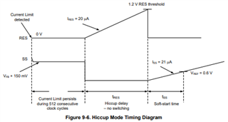
Could you show the timing diagram in this thread to explain the basic HICCUP mode behaver and the behaver in several cases which are described in 9.3.15?

Best Regards, Taki

  • Hello Taki,

    Let me look into this and see if we have an internal waveform of this. 
    Otherwise I can check it on the LM25143EVM and report back with the hiccup waveform image. 

    Regards,

    Jimmy

  • Hello Taki,

    See below the waveform for VOUT and SW during hiccup condition. 

    The during of the switching is around 400useconds. Then since the device still senses that the output voltage is shorted to GND, it will turn off and wait several cycles (measured roughly 12.8ms) before it attempts to startup again. This is what is considered hiccup mode.

    Regards,
    Jimmy