This thread has been locked.
If you have a related question, please click the "Ask a related question" button in the top right corner. The newly created question will be automatically linked to this question.
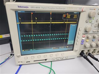
As you can see that there are two waveform in the oscilloscope. Top one is the output of the gate driver first channel output OUTA (yellow in color) and the below one is the driver input given from the STM microcontroller ( blue in color). why the yellow one has less number of pulses than the blue one?
Hi Suresh,
Thank you for your interest in this part!
Would you be able to provide some details of the schematic and waveform captures of VDDA and OUTB if channel B is also being driven?
This will be greatly helpful in finding the source of the issue.
Regards,
Hiroki
VDDA is 15v and VSSA is -8.7v. I haven't taken the output of OUTB. I shall measure and post it later. Interestingly the pspice simulation works fine. But only the problem is in the real hardware.
Is there any private channel where i can explain my schematic. I cannot post it in public.
Hey Suresh,
I reached out to you privately to help through email. Closing the thread here.
Thanks!
Hiroki