This thread has been locked.

If you have a related question, please click the "Ask a related question" button in the top right corner. The newly created question will be automatically linked to this question.

TPS61094: TPS61094 issues

Part Number: TPS61094

Hi

Please help me with solution issues that i have found during my bring up of board with TPS61094DSSR.

My design based on TPS61094D as UPS, the TPS61094D exist between SoM and DC to DC.

I have two issues:

1. According to your data sheet

My input should be high the output at least 100mV in order to start charging the super capacitor, but what i found during my measurements that delta should be at last 180-200mV (my current load request 700-900mA).

what should i do in order to reduce delta between Input to output ?

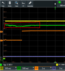
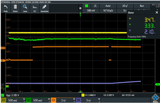
2.  During my output current to load, 700-900mA, exist too much ripples on output, see green line on plot below.

Yellow line is a input power to UPS (TPS61094D)

Blue line is a voltage on super capacitor.

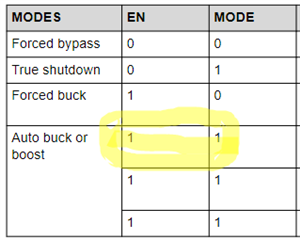
Orange line is EN line - GPIO that short the EN and MODE to one wire.

Vin = 3.47V , Vout to load is 3.33V

the question is:

a. why exist so many ripples on output and how can I smooth them ?

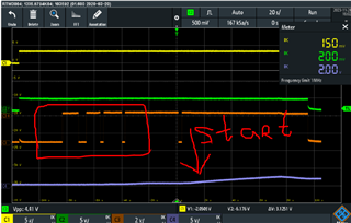
b. why the super capacitor charging start after 170 sec and not immediately after EN is in "high"??

Thank you

Ilya

  • Hi llya,

    Thanks for reaching out.

    Could you please share your schematic? I want to check the configuration like ICHG VCHG OSEL.. Thanks.

    Regards,

    Nathan

  • Hi llya,

    Thanks for sharing. Let me check it in our bench and then give you feedback later.

    Regards,

    Nathan

  • Hi llya,

    The 100mV is not an accurate value, the threshold has variation chip by chip, 100mV is just a reference value. Similarly, the VOUT > setting VOUT is not a accurate condition, neither. The condition may be VOUT > setting VOUT + 30mV, just take an example. 

    And for 2nd question, I think the charging doesn't start after 170s, it starts after you toggle EN/MODE again, and when you toggle again, the VOUT seems to be a little higher so the charging starts.

    Does the SUP voltage equals 0V? If that, it will stuck in forced bypass mode even if you set the MODE to automatic transition mode, you need to set the MODE to forced buck first and then set to automatic mode, or keep SUP voltage higher than 0.6V, or give a little higher VIN voltage.

    Please let me know if you have more questions.

    Regards,

    Nathan

  • Hi Nathan

    1. In order to clarify, the dealt of charging is according to Vout setting? (resistor between the OSEL pin and ground that define Vout once Vin failed).

    For my solution, i need Vin_device= Vout_TPS6109 =3.3-3.40V

    i set Vout to 3V3. (OSEL, R=4.75 kOham). what should i do in order to be compliance for your requirements -"The condition may be VOUT > setting VOUT + 30mV, just take an example."

    2. Please suggest why your output is not sables ? why exist so many ripples on output and how can I smooth them ?

    I think all problem cam from that, that Vout not sable

    3. Pay attention to that plot, see how many times we set EN and MODE to "1" in order tart charging the SUP, why it happened?

    Thank you

    Ilya

  • Hi llya,

    1.I guess you want to keep VOUT be 3.3V-3.4V no matter what is the VIN present, right? If that, set OSEL to 3.3V is ok for your application. By this way, when VIN is lost, the TPS61094 will boost VOUT to 3.3V.

    What I mean before is that the buck charging enter condition not boost enter condition.

    2.I found that in the second figure (in question 3) you provided, the VOUT is stable, so can the unstable waveforms be re-appeared? Is it possible caused by test method or the e-load characteristics?

    Because during the unstable time, the device operate in forced by-pass mode, the VOUT is connected with VIN directly, our device doesn't control VOUT at this time. In our EVM, I also test with the same condition and don't find any unstable behavior.

    3.Personally I think the charging doesn't start at the time you pointed, the charging seems to start before this time because I find the SUP voltage increase a little before this time. Could you please test the charging current from SUP pin to super capacitor? This is a more accurate signal that can show if the charging starts or not. (Or if you don't have current sense probe, you can test the SW waveforms, the time it starts to switch is the time it starts to charge)

    Regards,

    Nathan