This thread has been locked.

If you have a related question, please click the "Ask a related question" button in the top right corner. The newly created question will be automatically linked to this question.

BQ76930: BQ76930 failed to read cell voltage and temperature values

Part Number: BQ76930

Hi 

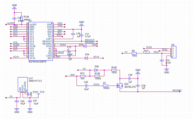
The customer design with BQ76930, the customer designed two versions of the circuit.

The first version was successful, but the second version had problems. The only difference between the two versions was the change of the power supply circuit to 12V.

Attached the schematic.

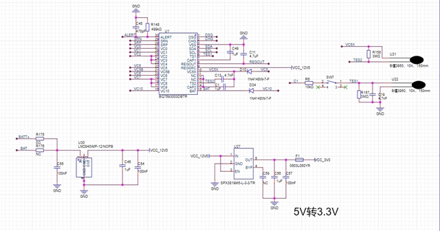
The registers all can be read, but the cell voltage is almost 0, and the temperature value is 0xFF.

Please give some suggestions.

Thanks

Star

  • Hi Star,

    Do you have the full schematic to share?

    Also, are they seeing any faults in the registers, such as XREADY?

    Regards,

    Max Verboncoeur

  • Hi Max

    Thanks for your reply.

    Attached the schematic

    2133.原理图.pdf

    Please help check it.

    Thanks

    Star

  • Hi Star,

    While I check the schematic, could the customer check two things in parallel:

    1. Is the device experiencing an XREADY fault as described in Section 5 of the Design Considerations document (link)?
    2. To rule out any assembly issues, could they check the voltage at all of the pins is within expectations?

    And one question I have: is this a fault in a single board, or are multiple boards showing this behavior?

    Regards,

    Max Verboncoeur

  • Hi Max

    Thanks for your reply.

    1, XREADY is set, and can't clear.

    2, It was measured that the cell voltage at the chip is normal, the REGOUT output is 3.3V, and the REGSRC input is 12V;

    5 PCBs all had this problem

    Please give some suggestions.

    Thanks

    Star

  • Hi Star,

    I recommend reading and following the steps given in Question 1.12 of the FAQ document for this device (link) to clear the XREADY fault.

    Regards,

    Max Verboncoeur

  • Hi Max 

    Thanks for your help.

    Replace the 24V to 12V power supply circuit with the recommended circuit and it works normally. The schematic diagram is as follows:

    The maximum operating current is about 80A, and the rated operating current is 40A.

    What should we set the thresholds of overcurrent protection and short-circuit protection to?

    Waiting for your help.

    Thanks

    Star

  • Hi Star,

    That is mostly in the hands of the system designer to decide. Typically, the OCD protection will be set just above the maximum expected current, and the SCD will be set to a current that the system designer wants to have a rapid response to, generally outside the range of any normal transients so that the device does not overreact to transients such as inrush current during the DSG FET turn on.

    Section 9.2.2 of the datasheet walks through an example design process and may be helpful to reference.

    Regards,

    Max Verboncoeur

  • Hi Max

    Thanks for your help.

    Why we can not use an additional LDO to replace the recommend 24V to 12V power supply circuit

    What is the output performance of the recommended power circuit? 

    Waiting for your reply.

    Thanks

    Star

  • Hi Star,

    The LDO should be fine to use in theory. It may be that the external supply is initializing too slow or too late.

    XREADY indicates that the device is not initializing properly and the supply not powering the pin in time could explain the fault.

    They could try measuring the CAPx capacitors to see if everything is being powered correctly.

    Regards,

    Max Verboncoeur