Hello,
Background of FuelGaugeIC:
-In our device, Fuelgauge IC is a system side application and is not mounted on the battery pack.
-Battery design capacity 1230mAh
-FS file based on new battery
-Reserve capacity = 350mAh
-FS file based on new battery
-Reserve capacity = 350mAh
Question:
We are verifying whether the battery meter can be correctly matched during the battery aging process. There are two questions that need to be answered:
1. We want to calibrate the battery midway. To calibrate the battery, we need to unplug the battery from the device, which will cause the FuelGaugeIC to lose power.
Is there a way to keep the electricity meter in its pre power off state?
The current registers: subclassID 82, 89, 105, and 109 will be periodically read and saved (RA table and Qmax have not changed during testing), and the saved values will be loaded when the FuelGaugeIC is powered on.
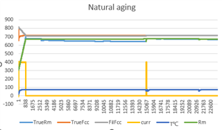
2. Currently running for 19 days, the filtered FCC predicted by the electricity meter has been around 718mAh. What is the reason?
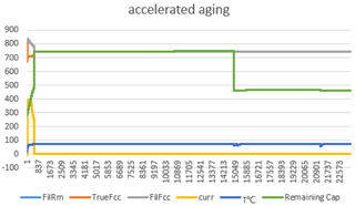
There are two types of tests: accelerated aging test and natural aging test.
Accelerated aging test conditions:
Test temperature: 70 ℃
Equipment quantity: 3 units
Test steps:
Step 1. Charge to SOC=85%
Step 2, discharge to SOC=51%
Step 3, loop sequentially Step 1->Step 2
We are verifying whether the battery meter can be correctly matched during the battery aging process. There are two questions that need to be answered:
1. We want to calibrate the battery midway. To calibrate the battery, we need to unplug the battery from the device, which will cause the FuelGaugeIC to lose power.
Is there a way to keep the electricity meter in its pre power off state?
The current registers: subclassID 82, 89, 105, and 109 will be periodically read and saved (RA table and Qmax have not changed during testing), and the saved values will be loaded when the FuelGaugeIC is powered on.
2. Currently running for 19 days, the filtered FCC predicted by the electricity meter has been around 718mAh. What is the reason?
There are two types of tests: accelerated aging test and natural aging test.
Accelerated aging test conditions:
Test temperature: 70 ℃
Equipment quantity: 3 units
Test steps:
Step 1. Charge to SOC=85%
Step 2, discharge to SOC=51%
Step 3, loop sequentially Step 1->Step 2
Natural aging test conditions:
Test temperature: 70 ℃
Equipment quantity: 3 units
Step 1. Charge to SOC=95%
Step 2, Battery Relax, wait for the battery to self lose to SOC=91% (battery self loss current below 1mA)
Step 3, loop sequentially Step 1->Step 2
Best Regards