This thread has been locked.

If you have a related question, please click the "Ask a related question" button in the top right corner. The newly created question will be automatically linked to this question.

TPS560430: 5V output drops when load is applied

Part Number: TPS560430
Other Parts Discussed in Thread: SN65HVD235, TLV9154

Hello,

we intend to use the TPS560430X to convert 24V Vin to 5V. From these 5V we use an LDO TPS70933 for 3.3V.

We need the 5V for some OpAmps and the 3.3V only to power a small uC and a CAN-Tranceiver with around 30mA.

The Design for the TPS560430 was done with the help of WEBENCH.

We tested the design without any load. Therefor no other parts, exept those needed for the supply, were placed. In this case we achieved an output of 5.05V and 3.28V, which is good.

As soon as we added some loads, the 5V dropped to around 4V. The current remained at 5V remained low at a few 10mAmps. No devices ran hot.

I tried swaping the converter, increased the output capacitance, enlarged and lowered the inductance. All of that did not help.

Any idea why the TPS560430X is not regulating the output voltage to the desired 5V?

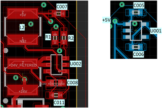
I added a screenshot of the schematics.

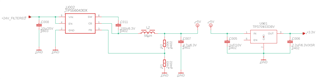
Not sure if it is needed, but on 3.3V there is the uC TMS320F3800137 and a CAN-Tranceiver SN65HVD235. On 5V there is only one TLV9154.

Thansk you for any answers.

  • Hello

    Can you provide images of your PCB layout.

    Also, please provide 'scope shots of the voltage on the SW pin and the CB pin during good an bad behavior.

    Your inductance is somewhat large and output capacitance somewhat small, compared to the data sheet 

    reccomendation.

    Thanks

  • Hello, thanks for your reply.
    This is the Layout:

    And here are some scope shots without load (Ch1: SW, Ch2: CB):

    I could not reproduce a good 5V-Output. This time even without load I only achieved about 4.7V

    With load (Ch1: SW, Ch2: CB):

    Here the output was at 4V.

    You mentioned the inductance and the output capacitance. I changed the inductance to 11uH with about 0.4ohm. I also changed the capacitance to 14.7uH. This did not change its behavior.

    Thank you

  • Hello

    I think your PCB layout will need some attention.

    It is best to route the power components with wide and short traces.

    This is especially true of the grounds and the input capacitor, boot capacitor, and output filter.

    It is best to follow the recommended data sheet layout.

    Also, you did not show the input filter in your schematic.

    You might try to short out that inductor and see if the issue is improved.

    Thanks

  • The issue was found. The CB and SW Pin were swapped. After changing that, it worked fine.
    Thank you for your help.