This thread has been locked.

If you have a related question, please click the "Ask a related question" button in the top right corner. The newly created question will be automatically linked to this question.

TPS40400EVM-351: GUI software does not recognize TPS40400

Part Number: TPS40400EVM-351
Other Parts Discussed in Thread: TPS40400, USB-TO-GPIO2,

Hello!

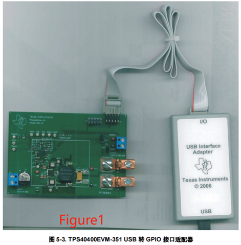
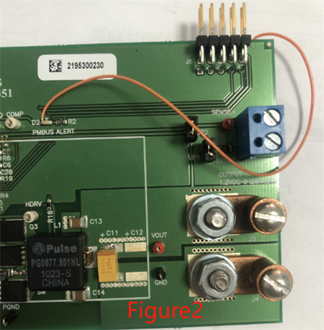
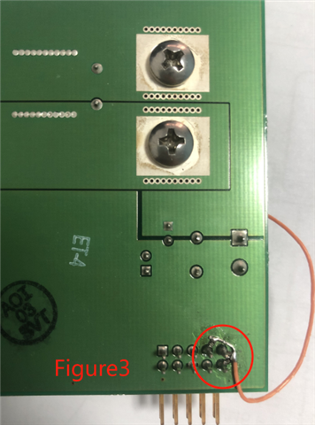
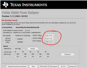
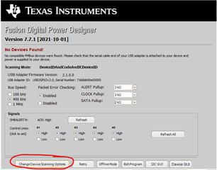
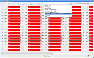
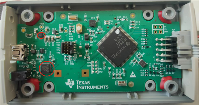
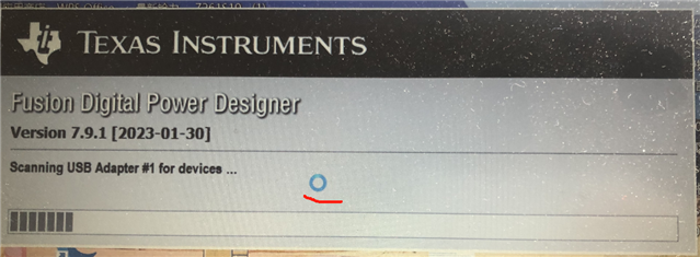
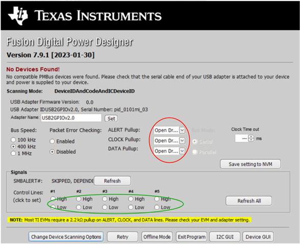
Connect the TPS40400ENM-351 test board and adapter as shown in Figure 1, at the same time, apply 5V power to the input of the test board, then connect the USB interface of the adapter to the computer, and open the Fusion GUI software, which can never recognize the TPS40400. If the voltage of about 3V is connected to three endpoints through 2.2KΩ resistors as shown in Figure 2 and Figure 3, the Fusion GUI software can recognize the TPS40400. Why is this?


  • Hello, 

    can you please follow the 5.3 Recommended Test Setup from the user's guide step by step and let me know if you still having issues. Technically you do not need any modification to the EVM to make this work. 

    https://www.ti.com/lit/ug/sluu535a/sluu535a.pdf?ts=1709324981173&ref_url=https%253A%252F%252Fwww.ti.com%252Ftool%252FTPS40400EVM-351

    In you figure 3, is the wire connected to all three connectors?

    Thanks! 

    Tahar 

  • Hello, I did follow 5.3 and 5.4 in the user's guide step by step, but the GUI interface always shows NO DEVICES FOUND.

    In figure 3,the wrie is connected to all three conncectors.

  •  

    The USB-TO-GPIO adapter that you are using has internally programmable pull-ups.  These are configured with firmware inside the USB-TO-GPIO adapter and may be set to OPEN in order to use external pull-ups.  The most common reason why you would see no devices found with no external pull-ups and find a device with an external pull-up would be:

    1) The USB-TO-GPIO adapter's internal pull-ups are configured to "OPEN"

    2) The USB-TO-GPIO adapter's internal 3.3V source is in current limit (<100mA)

    The USB-TO_GPIO adapter also has several scan options.  The TPS40400 uses an MFR_SPECIFIC (command code FCh) Read Word "DEVICE_CODE" to identify itself to FUSION.  If the scanning options are not set correctly, providing external pull-ups would not fix the issue.

    To access these options, when FUSION DIGITAL POWER DESIGNER reports no device found, check the pull-up settings in the FUSION GUI

    These should all be set to 2.2kΩ or lower.

    For scanning options, on the lower left, find Change Device Scanning Options

    For the TPS40400, you need to make sure the DEVICE_CODE is selected for the address you are using.  For more general use, TI recommends setting all addresses to use ID_CODE, DEVICE_CODE , and IC_DEVICE_ID.

    If you are still having issues, please take screen shots of both the "No Device Found" screen and the Scanning Options screen so we can help you debug the issue you are seeing.

  • Ok, I understand what you said, but now there is a problem. After I connected it in the way shown in Figure 2 and Figure 3, the software can recognize TPS40400. I have been following this way ever since, but after using it for a while, the adapter suddenly broke down. I bought two adapters in total, and now both adapters are broken. After disassembling the adapters, I found that when the USB interface was connected to the computer, the two devices circled in the figure were very hot,the temperature can reach above 130℃ in an instant. I want to know whether the damage of the adapter is related to my external voltage of 3.3V Because the value of the adapter is relatively high, I can't continue to buy new ones. If I replace the device with severe fever, can I repair it? Please give me some suggestions. Thank you!

  •  

    1) Figure 1 shows a USB-TO-GPIO adapter from 2006, the internal picture you have just shared is from a USB-TO-GPIO2 adapter from 2022.  They are internally different.

    2) In the USB-TO-GPIO2 adapter, U15 is a 5V to 3.3V LDO which provides the 3.3V source for the internal functions of the USB-TO-GPIO2 adapter.  If the 3.3V output of the adapter (Pin5) is connected to another 3.3V source, it could cause damage to U15.

    3) In the USB-TO-GPIO2 adapter, U17 is a USB interface IC, which is partially powered by U15.  Damage to U15 or overvoltage on pin-5 of the GPIO connector could result in damage to U17.

    I want to know whether the damage of the adapter is related to my external voltage of 3.3V

    It could be related to your connection of BP3 from the TPS40400 to the output pins of the GPIO connector.

    It could also be related to a ground differences between the TPS40400EVM board and the computer connected to the USB-TO-GPIO2 adapter, so I would check those grounds as well as removing the external pull-up to BP3

    If I replace the device with severe fever, can I repair it?

    I can not say, there may be damage to other devices connected to the 3.3V supply in the USB-TO-GPIO2 

    Once you have enabled the internal 2.2kΩ pull-up resistors on the USB-TO-GPIO2, you should not need the external pull-up from BP3 of the TPS40400.

    For the external pull-ups, I would recommend double checking the soldering and resistors by measuring the resistance from BP3 to CLK, DAT, and ALERT# with an ohmmeter.

  • Hello,Peter James Miller!

    Thank you for your reply!

    1. Today, after I replaced U15 and U17 in the adapter, the adapter can work normally. Then I connected the adapter to TPS40400EVM-351 evaluation board, and there was no external power supply of 3.3V After opening the GUI software, the following interface was displayed

    The software status is corresponding, which is always the case when restarting the software for many times. After unplugging the USB interface of the adapter, the interface shown below will be displayed

    and then the red circled area was changed to 2.2KΩ,but the place circled in green can't be selected. Click to try again and then return to this interface. The place circled in red is still OPEN, and the device _ ID & device _ code & IC _ device _ ID has been selected for Change Device Scanning Options. I don't know why the place circled in green can't be selected.

    2. Now a product I developed uses TPS40400 chip, and the prototype is debugged with GUI software and the adapter. If it is mass-produced, how to burn the debugged program into the chip? Does TI have a special programming device? Or the solution of batch burning program?

  •  

    First, I would recommend downloading the newest version of FUSION DIGITAL POWER DESIGNER here - https://www.ti.com/tool/FUSION_DIGITAL_POWER_DESIGNER 

    Today, after I replaced U15 and U17 in the adapter, the adapter can work normally.

    I am very glad to hear that nothing else in the adapter was damaged and it is now working correctly.

    I don't know why the place circled in green can't be selected.

    These are selecting the state of the 5 digital lines.  They are not initialized at this point.  I will ask our software team to look into it.

    and then the red circled area was changed to 2.2KΩ,but the place circled in green can't be selected. Click to try again and then return to this interface. The place circled in red is still OPEN, and the device _ ID & device _ code & IC _ device _ ID has been selected for Change Device Scanning Options.

    After changing the settings to 2.2kΩ pull-ups, click the "Save Settings to NVM" button to store those values to the NVM of the adapter.  That should activate the pull-ups and retain that setting even if the USB connector is disconnected.

    2. Now a product I developed uses TPS40400 chip, and the prototype is debugged with GUI software and the adapter. If it is mass-produced, how to burn the debugged program into the chip? Does TI have a special programming device? Or the solution of batch burning program?

    the FUSION suite of programs includes a production script tool that can use the adapter to execute a comma separated value (CSV) formatted script (one of the export formats selectable from FUSION) to write a series of commands to the connected bus.  A single adapter can be connected to many devices / boards in parallel.  With the same address uses on all connected boards, all of the devices will be written at the same time.

    Depending on the speed, parasitic capacitance, and number of boards being written in parallel, the pull-up resistance may need to be lower than 2.2kΩ.  The TPS40400 is designed to support pull-up currents upto 4mA.

    The same script could also be used by alternate hardware to generate the PMBus clock and data signals, but that would not be able to use TI's manufacturing script too, it would need it's own script parsing tool that works with the hardware to be used.

    TI does not offer a programming socket that can program a part outside of a board, though one could be built.

    TI does not offer a different custom programming adapter from the USB-TO-GPIO2 

  • Hello,Peter James Miller!

    Now I have encountered a new problem. When I import the debugged program into a new chip, the interface in the diagram will appear, prompting that there is an error. There are more than a dozen parameters between the set program and the original program in the new chip. If I change the parameters one by one, it is no problem, but it is not possible to directly import the set program. I don't know what is wrong.

  • It sounds like the dongle is trying to send the PMBus commands faster than the TPS40400 can respond.  Try reducing the BUS speed in the adapter settings to 100kHz instead of 400kHz to give more time for the TPS40400 to keep up with the commands.