- Ask a related questionWhat is a related question?A related question is a question created from another question. When the related question is created, it will be automatically linked to the original question.
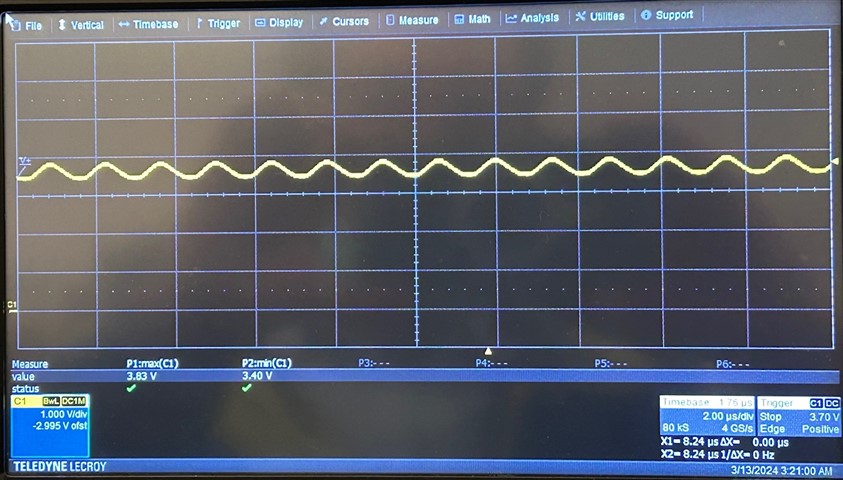
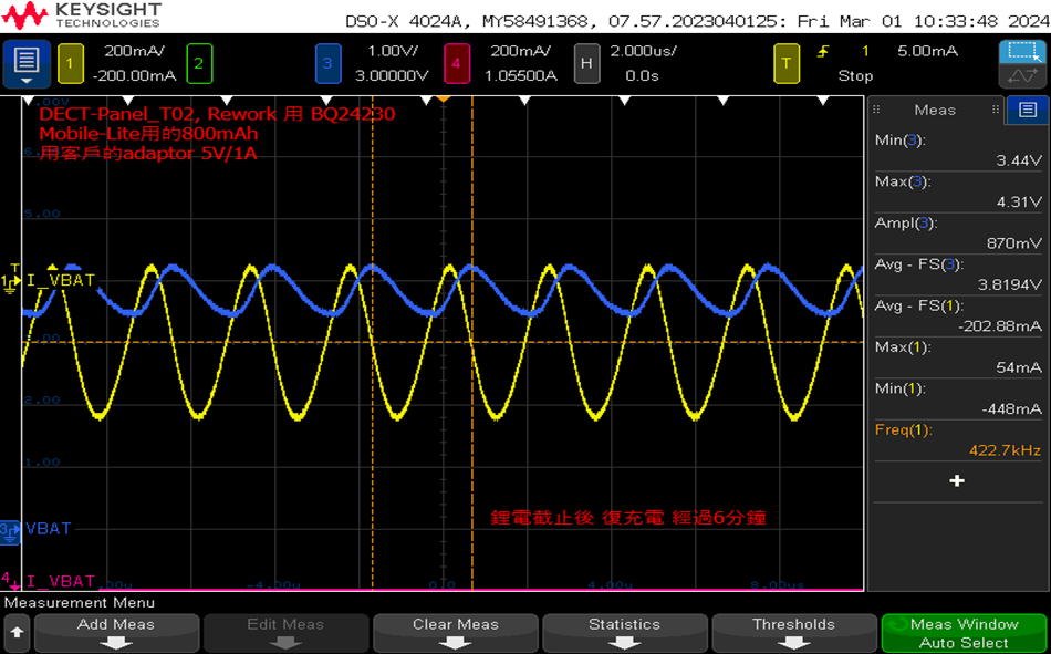
We do the deep discharge while one night without adaptor input. We find the VBAT become unstable after I insert the adaptor 5Vdc. The VBAT and IBAT show in below.
I know the Vlowv is the same as battery cut-off voltage. But the VBAT in the waveform is around 3.44V(min) ~ 4.31V(max), shape as SIN wave. The VBAT is above Vlowv, the charger should be constantly charging the battery. May I learn from you why have this problem? Thanks
BR,
Gary
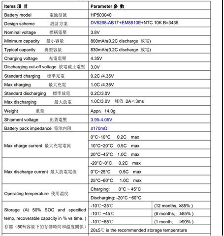
Battery spec.