This thread has been locked.

If you have a related question, please click the "Ask a related question" button in the top right corner. The newly created question will be automatically linked to this question.

TPS6287B10: How should the I2C interface be connected when VSET1 and VSET2 pins are used to set the default output voltage

Part Number: TPS6287B10

Dear TI Teams,

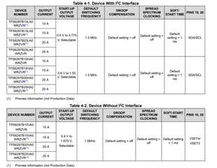
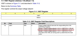
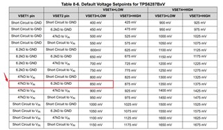
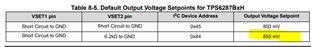
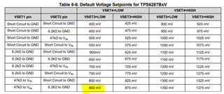
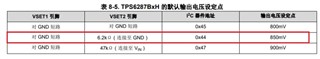
We are plan to use TPS6287B10 to achieve 3.3V input and 0.85V/10A output. Form the datasheet we can learned that the VSET1 and VSET2 can set the defult output voltage to 0.85V, but we don't know how should the I2C interface be connected at this time. Can you help to confirm it?

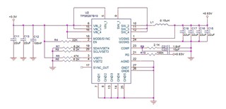
We also designed the following circuit based on the pin definitions on the datasheet. Can you help check if there are any problem?

Thanks,

Kind Regards

  • Hi, 

    Do you want to use a I2C version of the device or the non I2C version?

    You will either have SCL/SDA pins or VSET3/VSET4 pins in the device. 

    If you would like to use the I2C version, then you can connect the pins to I2C bus through a controller(section 8.5). During the startup, VSET1 and VSET2 sets the startup voltage and then during operation, the output volatge can be changed using I2C. 

    Thanks!

    Best regards

    Sneha 

  • Hi Sneha,

    If we using the I2C version, and just need the default 0.85V output, the SDA and SCL must be used for I2C communication? If we set the bit[3:2] to 01b, the VSET[7:0] need to set to 14h?

    I also noticed that the non I2C version, if we need to output 0.85V, do we directly follow the suggestions on the table below for circuit design?

    Thanks,

    Kind Regards

  • Hi,

    You can use the below setting for the I2C device:

    For non-I2C below setting:

    Thanks!

    Best regards

    Sneha