This thread has been locked.

If you have a related question, please click the "Ask a related question" button in the top right corner. The newly created question will be automatically linked to this question.

BQ21040: Disconnect Load While Charging and Prevent against reverse battery Polarity

Part Number: BQ21040
Other Parts Discussed in Thread: TPS61288, CSD13380F3, , TPS22959, BQ2980

System Block Diagram

Hello,

I am very new to this, but would like to get your help and build up my knowledge.

My Application is to make portable escape room puzzles that has on board solenoid lock. The puzzles is managed using Arduino, and I am designing a single Li-ion Battery Circuit that has required protections for my application.

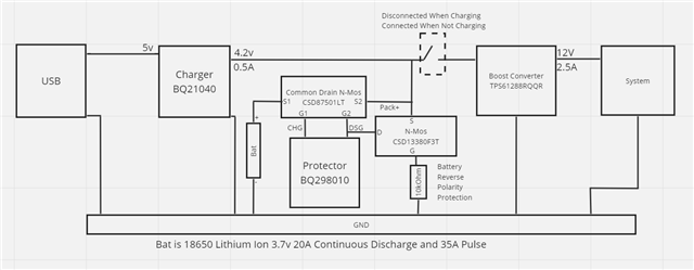
The system requirements is 12v and 2.5A, I am using a 3000mAh 3.7 18650 Battery that is capable of 20A Continuous discharge and can withstand a pulse current up to 35A. The system is to have an on board charger to charge the battery, a protector to protect against common battery faults and a boost converter to provide the required voltage and current.

As the block diagram shows I have connected BQ21040 linear charger to output 0.5A which is used to charge the battery (although the battery can accept up to 4A with 2A ideal charging current), then the battery is connected to BQ298010 for the protection functions which drives a common drain dual NMOS, the CSD87501LT, which then is to be connected in parallel to the boost Converter TPS61288 which shall deliver the 12v and 2.5A. One additional thing is I have added NMOS CSD13380F3 with a resistor to protect against reverse battery polarity as advised in another post in this form.

My questions are as follows:

1) is my reverse battery polarity circuit correct?

2) I want to have a switching circuit to prevent discharging while charging the Battery (by disconnecting the load) as it is clearly advised against to have the load in parallel with the battery by the BQ21040 IC Datasheet how I can achieve that?

3) Can the TPS22959 load switch be used for this application(Disconnect Load While Charging)? and if so how to connect it? or a circuit of PMOS and NMOS can do the trick and how to implement that?

4) Final Question is it okay to have a common ground for all the components? specially that I have a switching elements on my circuit and plan to have them all except for the load on the same PCB? 

Thanks in advance for the help and sorry if my questions are stupid and if I did not follow the forum rules and about my not good English.

  • Hello,

    1) Please refer to the attached document for help on reverse battery polarity: https://www.ti.com/lit/an/slva139/slva139.pdf?ts=1710882739610&ref_url=https%253A%252F%252Fwww.google.com%252F

    2) The CHG/ pin will go low to indicate charging and high to indicate charge done or charge complete. This is available to accomplish your logic goals.

    3) You will need to make a separate post with regards to the TPS22959 specifically for help on that.

    4) A common ground is needed, however careful creation of the connection path is needed. Please test and design according to your application.

    Regards,

    Mike Emanuel

  • Hello Mike,

    thanks for you prompt reply.

    1) thanks for sharing the application paper but it is confusing as it is a little bit different approach than what is implemented on one of TI’s evaluation boards, as advised on another post in this forum, it was referred to the bq40z50evm and specifically to q4 and r4 which is not connected to the power bath in the same sense as the shared paper, so can you please advise what is wrong with the approach I adopted from bq40z503evm.

    Edit: the forum post I am referring to

     e2e.ti.com/.../bq2980-battery-side-reverse-polarity-protection

    2) I will explore using this pin as the logic pin for my switch although I am not sure what will be the pin status if The charger is disconnected and how will it affect my switch circuit 

    3) sure will do.

    4) thanks a lot but is there any resources for how to implement the connection paths, I got confused mainly because of the layout section on the bq2980 data sheet when separate grounds is mentioned.

  • Hello,

    1) The implementation seems correct. However, please open a separate thread for the bq40z50evm to ask the application reasoning on the gauge board and whether or not your implementation is correct for the gauge and pack. Please test according to your application.

    4) Please follow the layout guidelines as shown in Section 11.1 and 11.2 of the datasheet. We require the separation.

    Regards,

    Mike Emanuel