This thread has been locked.

If you have a related question, please click the "Ask a related question" button in the top right corner. The newly created question will be automatically linked to this question.

BQ25672: Unable to charge.

Part Number: BQ25672

Hello,

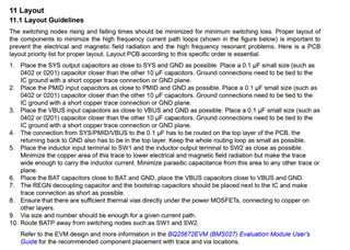
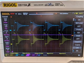
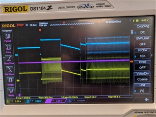
We have recently integrated the BQ25672 into a design and we are experiencing trouble with charging.

The design is based on a 2S battery configuration. We are using either 9V or 12V to charge. The system is connected to a host processor, but we are finding that there are issues with or without the host active.

The trouble is that the system will not charge.

During our investigation we have found a series of odd things occur:

1. We have seen the VBUS_OVP_STAT and VBAT_OVP_STAT flags go high.

2. We have seen the HIZ-Mode bit turn on, and refuse to turn off unless we remove all power. We have even tried using the I2C host to write the bit, but still cannot get the battery to charge.

3. We have sometimes had luck plugging in a 9V adapter, when a 12V adapter wouldn't work. But over time we are finding that even the 9V adapter stops working.

4. We have sometimes had luck with removing all power, then plugging in the battery, then plugging in the power supply. However, if you unplug and plug the power supply in, eventually it will stop working.

Out of 4 prototypes that all worked to begin with, only 1 is now working, and I am skeptical that it will continue to work. The rest of them no longer work, even when attempting the above tricks.

When reviewing the registers, the IC is aware that there is power present, through a "unknown 3A adapter" and that the power is good. So from what I can tell, the system should charge, but it won't.

I've seen notes in the forum about the need for the TVS on the battery and a snubber on the power input, but am wondering if that is required for a 2S configuration with a 9V / 12V power supply.

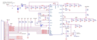
Below is my schematic, the host system is not shown, but I'm hoping that it isn't an important factor. Even when the host is held in reset, we are still unable to charge.

Any assistance you can give me would be greatly appreciated.

Thanks,
Jason

  • I would just like to add a couple of notes:

    - The REGN output is turned off. There is 0V on this output.

    - I am unable to power the load from the VBUS.  Even when I remove all power and try to plug power in again through VBUS it will not start the load output.

  • After updating my host software, I've been able to get at least some more information on what is happening.

    On this specific IC I'm working with (which doesn't work with a 12V DC adapter), I've found that I am getting a VBUS_OVP_STAT flag appearing every time I try to start the charger. I've monitored the voltage with a scope and have found that the maximum voltage is 12.7V. This is no where near the 26V that is programmed into the chip. 

    I have done a dump of the registers and the REG10_Charger_Control_1 register is reporting 0x07. which confirms that the OVP is set to 26V.

    Can you comment on how this could be happening?

    Thanks,

    Jason

  • Hello Jason,

    I have a few questions/suggestions:

    Can you confirm that you followed the PCB layout guideline?

    What is your battery voltage/charge current?

    Best Regards,

    Christian

  • Hi Christian,

    I believe the recommendations were followed fairly well. We used 0603 parts instead of 0402 or 0201 parts due to what we prefer to build with at our facility.
    Attached are PDFs of our layout (top side and bottom side)

    The battery voltage is 7.4V (2x 3.7V cells in series).  The charge current is limited to 1A though the use if the ILIM_HIZ. On the schematic R29 is not correct. During our testing it was modified to be 200k, which would limit between 0.75A and 0.92A depending on the variation of REGN. This could be lowered if required.

    Our wall wart that we use for charging will be either 9V or 12V. With a 1A current limit.

    Thanks,
    JasonCharger - Top Side.pdfCharger - Bottom Side.pdf

  • I'm not sure if it helps, but here is a scope capture (Switching 0.2A charge.jpg) showing the system with a 12V adapter, charging the battery with 0.2A of current. 

    There is another scope capture of the charge starting with the same conditions.

    Channel 1 is SW1
    Channel 2 is SW2
    Channel 3 is VSYS

    Thanks,

    Jason

  • Hello Jason,

    I'm not able to open the scope image.

    Best Regards,

    Christian.

  • Hi Christian,

    I suspect that's because I forgot to attach them.

    12V VBUS Switching:

    /resized-image/__size/320x240/__key/communityserver-discussions-components-files/196/Switching-0.2A-Charge.jpg

    12V VBUS Startup:

    /resized-image/__size/320x240/__key/communityserver-discussions-components-files/196/7774.Startup.jpg

    When I use a 9V power supply for VBUS, the startup looks quite different. 
    It also starts right away and doesn't flicker on and off like the 12V does.

    9V VBUS Startup:

    /resized-image/__size/320x240/__key/communityserver-discussions-components-files/196/Startup-9V-Adapter.jpg

    Thanks,
    Jason

  • Hello Jason,

    Can you provide your register values?

    Best Regards,

    Christian.

  • Hi Christian,

    The following is a dump of the registers.

    u8DummyReadArray is my array name.
    The [XX] is the register address.
    The uint8_t is the variable size
    Then we have the value in hex
    Finally my RAM address, which isn't at all important in the context of what were looking at.

    My apologies that it isn't in a nice format for you to read.

    This capture was taken the moment that the software hit a breakpoint reporting that there was a VBUS_OVP_STAT flag that was set.

    u8DummyReadArray[0] uint8_t 0x12 (Hex) 0x2000cc5c
    u8DummyReadArray[1] uint8_t 0x3 (Hex) 0x2000cc5d
    u8DummyReadArray[2] uint8_t 0x48 (Hex) 0x2000cc5e
    u8DummyReadArray[3] uint8_t 0x0 (Hex) 0x2000cc5f
    u8DummyReadArray[4] uint8_t 0x64 (Hex) 0x2000cc60
    u8DummyReadArray[5] uint8_t 0x68 (Hex) 0x2000cc61
    u8DummyReadArray[6] uint8_t 0x0 (Hex) 0x2000cc62
    u8DummyReadArray[7] uint8_t 0x4e (Hex) 0x2000cc63
    u8DummyReadArray[8] uint8_t 0xc3 (Hex) 0x2000cc64
    u8DummyReadArray[9] uint8_t 0x5 (Hex) 0x2000cc65
    u8DummyReadArray[10] uint8_t 0x63 (Hex) 0x2000cc66
    u8DummyReadArray[11] uint8_t 0x0 (Hex) 0x2000cc67
    u8DummyReadArray[12] uint8_t 0xdc (Hex) 0x2000cc68
    u8DummyReadArray[13] uint8_t 0x4b (Hex) 0x2000cc69
    u8DummyReadArray[14] uint8_t 0x3d (Hex) 0x2000cc6a
    u8DummyReadArray[15] uint8_t 0xa2 (Hex) 0x2000cc6b
    u8DummyReadArray[16] uint8_t 0x27 (Hex) 0x2000cc6c
    u8DummyReadArray[17] uint8_t 0x40 (Hex) 0x2000cc6d
    u8DummyReadArray[18] uint8_t 0x0 (Hex) 0x2000cc6e
    u8DummyReadArray[19] uint8_t 0x1 (Hex) 0x2000cc6f
    u8DummyReadArray[20] uint8_t 0x1e (Hex) 0x2000cc70
    u8DummyReadArray[21] uint8_t 0xaa (Hex) 0x2000cc71
    u8DummyReadArray[22] uint8_t 0xc0 (Hex) 0x2000cc72
    u8DummyReadArray[23] uint8_t 0x7a (Hex) 0x2000cc73
    u8DummyReadArray[24] uint8_t 0x54 (Hex) 0x2000cc74
    u8DummyReadArray[25] uint8_t 0x0 (Hex) 0x2000cc75
    u8DummyReadArray[26] uint8_t 0x4e (Hex) 0x2000cc76
    u8DummyReadArray[27] uint8_t 0x7 (Hex) 0x2000cc77
    u8DummyReadArray[28] uint8_t 0xa (Hex) 0x2000cc78
    u8DummyReadArray[29] uint8_t 0x1 (Hex) 0x2000cc79
    u8DummyReadArray[30] uint8_t 0x0 (Hex) 0x2000cc7a
    u8DummyReadArray[31] uint8_t 0x0 (Hex) 0x2000cc7b
    u8DummyReadArray[32] uint8_t 0x40 (Hex) 0x2000cc7c
    u8DummyReadArray[33] uint8_t 0x0 (Hex) 0x2000cc7d
    u8DummyReadArray[34] uint8_t 0x88 (Hex) 0x2000cc7e
    u8DummyReadArray[35] uint8_t 0x90 (Hex) 0x2000cc7f
    u8DummyReadArray[36] uint8_t 0x40 (Hex) 0x2000cc80
    u8DummyReadArray[37] uint8_t 0x0 (Hex) 0x2000cc81
    u8DummyReadArray[38] uint8_t 0x40 (Hex) 0x2000cc82
    u8DummyReadArray[39] uint8_t 0x0 (Hex) 0x2000cc83
    u8DummyReadArray[40] uint8_t 0x0 (Hex) 0x2000cc84
    u8DummyReadArray[41] uint8_t 0x0 (Hex) 0x2000cc85
    u8DummyReadArray[42] uint8_t 0x0 (Hex) 0x2000cc86
    u8DummyReadArray[43] uint8_t 0x0 (Hex) 0x2000cc87
    u8DummyReadArray[44] uint8_t 0x0 (Hex) 0x2000cc88
    u8DummyReadArray[45] uint8_t 0x0 (Hex) 0x2000cc89
    u8DummyReadArray[46] uint8_t 0x30 (Hex) 0x2000cc8a
    u8DummyReadArray[47] uint8_t 0x0 (Hex) 0x2000cc8b
    u8DummyReadArray[48] uint8_t 0x0 (Hex) 0x2000cc8c
    u8DummyReadArray[49] uint8_t 0x0 (Hex) 0x2000cc8d
    u8DummyReadArray[50] uint8_t 0x0 (Hex) 0x2000cc8e
    u8DummyReadArray[51] uint8_t 0x0 (Hex) 0x2000cc8f
    u8DummyReadArray[52] uint8_t 0x0 (Hex) 0x2000cc90
    u8DummyReadArray[53] uint8_t 0x2e (Hex) 0x2000cc91
    u8DummyReadArray[54] uint8_t 0x5a (Hex) 0x2000cc92
    u8DummyReadArray[55] uint8_t 0x0 (Hex) 0x2000cc93
    u8DummyReadArray[56] uint8_t 0x0 (Hex) 0x2000cc94
    u8DummyReadArray[57] uint8_t 0x0 (Hex) 0x2000cc95
    u8DummyReadArray[58] uint8_t 0x0 (Hex) 0x2000cc96
    u8DummyReadArray[59] uint8_t 0x0 (Hex) 0x2000cc97
    u8DummyReadArray[60] uint8_t 0x0 (Hex) 0x2000cc98
    u8DummyReadArray[61] uint8_t 0x0 (Hex) 0x2000cc99
    u8DummyReadArray[62] uint8_t 0x0 (Hex) 0x2000cc9a
    u8DummyReadArray[63] uint8_t 0x0 (Hex) 0x2000cc9b
    u8DummyReadArray[64] uint8_t 0x0 (Hex) 0x2000cc9c
    u8DummyReadArray[65] uint8_t 0x0 (Hex) 0x2000cc9d
    u8DummyReadArray[66] uint8_t 0x0 (Hex) 0x2000cc9e
    u8DummyReadArray[67] uint8_t 0x0 (Hex) 0x2000cc9f
    u8DummyReadArray[68] uint8_t 0x0 (Hex) 0x2000cca0
    u8DummyReadArray[69] uint8_t 0x0 (Hex) 0x2000cca1
    u8DummyReadArray[70] uint8_t 0x0 (Hex) 0x2000cca2
    u8DummyReadArray[71] uint8_t 0x0 (Hex) 0x2000cca3
    u8DummyReadArray[72] uint8_t 0x21 (Hex) 0x2000cca4
    u8DummyReadArray[73] uint8_t 0x0 (Hex) 0x2000cca5

    Thanks,
    Jason

  • Hello Jason,

    Thank you for this information, I would provide an update after I gather more information.

    Best Regards,

    Christian.

  • Hello Jason,

    Have you tried adding the TVS on the battery and a snubber on the power input? I recommend replacing the IC if you do this.

    You shouldn't have to add these, but for testing purpose I recommend testing to see if this resolves the issue. 

    Best Regards,

    Christian

  • Hi Christian,

    We tried the snubber on the power input. We did not try the TVS on the battery.

    We suspect that the issue is layout related. We added a wire between ground on the PMID caps and ground on the VBUS caps and found that the system is now cable to charge using a 12V power supply. 

    The decision has been made to redesign the board using a 4 layer design. We believe that given the high switching frequency, that our ground connections are just not good enough.

    Does this make sense?

    Thanks,
    Jason

  • Hello Jason,

    We suspect that the issue is layout related. We added a wire between ground on the PMID caps and ground on the VBUS caps and found that the system is now cable to charge using a 12V power supply. 

    That's good to hear.

    The decision has been made to redesign the board using a 4 layer design. We believe that given the high switching frequency, that our ground connections are just not good enough.

    Does this make sense?

    Yes, without a good ground connection the device can have an unpredictable behavior. I think based on your test with adding a wire between ground on the PMID caps and ground on the VBUS caps and now able to charge using a 12V power supply, this is most likly the issue.

    Best Regards,

    Christian.