This thread has been locked.

If you have a related question, please click the "Ask a related question" button in the top right corner. The newly created question will be automatically linked to this question.

LP876242-Q1: ESM cfg

Part Number: LP876242-Q1
Other Parts Discussed in Thread: AM2732, LP876242Q1EVM

Hi:

     When I enable the ESM function of this chip,and cfg as follows:

                             read PmicReg 0x31 regValue = 0x1
                             Write PmicReg 0x31 regValue = 0x21
                             read PmicReg 0x31 regValue = 0x21
                             read PmicReg 0x3a regValue = 0x21
                             Write PmicReg 0x3a regValue = 0x21
                             read PmicReg 0x3a regValue = 0x21
                             read PmicReg 0x90 regValue = 0x0
                             Write PmicReg 0x90 regValue = 0x20
                             read PmicReg 0x90 regValue = 0x20
                             read PmicReg 0x91 regValue = 0x0
                             Write PmicReg 0x91 regValue = 0x20
                             read PmicReg 0x91 regValue = 0x20
                             read PmicReg 0x92 regValue = 0x0
                             Write PmicReg 0x92 regValue = 0x40
                             read PmicReg 0x92 regValue = 0x40
                             read PmicReg 0x8f regValue = 0x0
                             Write PmicReg 0x8f regValue = 0x1
                             read PmicReg 0x8f regValue = 0x1
                             read PmicReg 0xa regValue = 0x22
                             Write PmicReg 0xa regValue = 0x33
                             read PmicReg 0xa regValue = 0x33

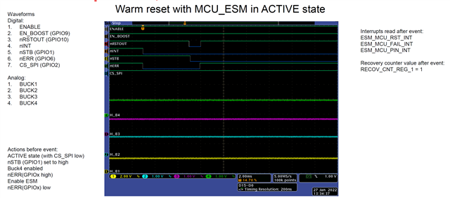
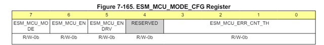
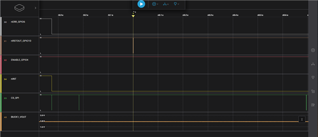
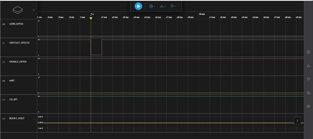
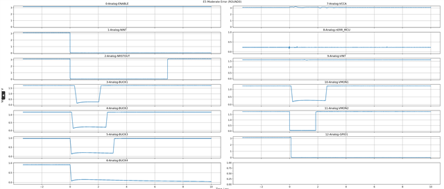
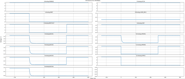
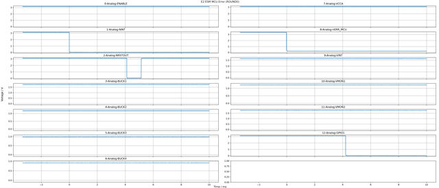
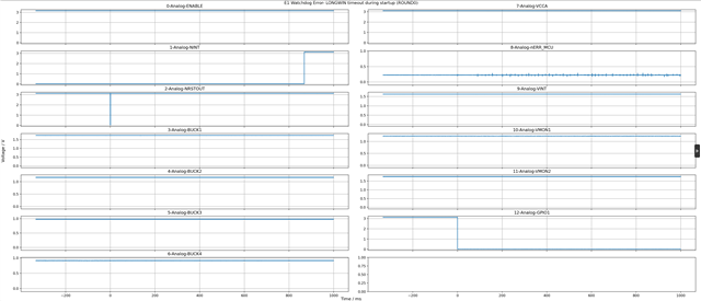
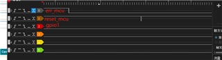
 Then the ERR_mcu is simulated to pull the foot. But GPIO1, and GPIO10, have no drop-down. May I ask whether the chip supports esm configuration like this? Is there any problem with my configuration? What the proper configuration should look like.

  • Hi,

     Then the ERR_mcu is simulated to pull the foot.

    What do you mean by foot?

    Yes ESM configuration is supportable but can you let me know what do you want to do ? are you testing to see if ESM works or not? if so can you also have a look at the following thread if that's what you also want to do? 

    https://e2e.ti.com/support/power-management-group/power-management/f/power-management-forum/1258876/lp876242-q1-12-mcu-esm 

    BR,

    Ishtiaque

  • Hi:

    hen the ERR_mcu is simulated to pull the foot. I mean use the tweezers to pull the ERR mcu pin low.

    the register I cfg is:

    0x31 regValue = 0x21
    0x3a regValue = 0x21
    0x90 regValue = 0x0
    0x91 regValue = 0x20
    0x92 regValue = 0x40
    0x8f regValue = 0x1

    then I use the tweezers to pull the pmic uERR_mcu pin low.but GPIO1 and GPIO1 0 are not pulled down

    thanks;

    zdd

  • Hi:

    0、1、2、regValue :
    read PmicReg 0x0 regValue = 0x0
    read PmicReg 0x1 regValue = 0x8E
    read PmicReg 0x2 regValue = 0xB0

    thanks

    zdd

  • Hi,

    Sorry for the delay. I was on sick leave. 

    Can you first let me know are you trying to enable level mode ESM or PWM ESM? 

    Based on above question, you need to follow the instructions given in datasheet on how to enable the ESM if for example it is level mode then you should check 7.3.9.2 Level Mode in datasheet. 

    And see the flow diagram below and follow that to get it done and point me to a step where you are stuck on the flow diagram.  

    BR,

    Ishtiaque 

  • Hi:

        The log display mode register 0x92 that I sent earlier is configured to be 0x04,it's level mode

    BR,

    zdd

  • Hi,

    GPIO6 is configured as nERR_MCU so are you pulling low signal of GPIO6 after correctly enabling the ESM level mode?

  • yes,I pulling low signal of GPIO6 after correctly enabling the ESM level mode。Can you give the configuration of all relevant registers for this usage. Let me try,to check for hardware issues。

  • Hi,

    I can try on the EVM but that will be done by end of this week. Can you probe the ESM signal and see whether it is fed correctly.

    I am wondering whether have you checked example waveform of ESM_MCU level mode use cases in datasheet.

    BR,

    Ishtiaque  

  • Hi,

           I use a multimeter to measure the err_mcu pin pin level,it's low . can you check the register value I configured, is there something wrong or missing.

  • Hi,

    I will check on EVM but this will be done by end of this week.

    Br,

    Ishtiaque

  • Hi,

    So according to following ESM MCU error test case done on LP876242-Q1, GPIO1 and GPIO10 ( 2-Analog-NRSTOUT) are going low when GPIO6 (Analog-nERR_MCU) is driven low. However, NRSTOUT comes back because this is warm rest.

     This is how it should behave. 

    Validation should be as following,

    1. Device is up and running with all regulators enabled. 
    2. GPIO1 is set 
    3. All interrupts cleared
    4. Set ESM_MCU_DELAY1
    5. Set ESM_MCU_DELAY2
    6. Drive NERR_MCU signal High 
    7. Enable ESM_MCU_EN by setting to 1
    8. Enable ESM_MCU_START by setting to 1
    9. Put down the NERR_MCU signal
    10. Now you should capture in scope the same behavior as above shown.            
  • Hi,

        Could you please give me your specific register configuration? I tried your method but failed.

  • Hi,

    Are you making sure that there are no interrupts pending? Can you share how are you doing? Can you show the oscilloscope capture or something. 

    Also can you just confirm that you are using LP876242B0RQKRQ1 device? Let me do something to show you but I guess you need to check first that there is no errors or interrupts pending while enabling the ESM and performing the task. 

    BR,

    Ishtiaque 

  • Hi:

        Let me show you my log:

     pmic Vesion
    read PmicReg 0x0 regValue = 0x0
    read PmicReg 0x1 regValue = 0x8E
    read PmicReg 0x2 regValue = 0xB0

    Clear INT_ESM 6c
    read PmicReg 0x6c regValue = 0x0
    Write PmicReg 0x6c regValue = 0x0
    read PmicReg 0x6c regValue = 0x0

    Clear INT_MISC 66
    read PmicReg 0x66 regValue = 0x1
    Write PmicReg 0x66 regValue = 0xFF
    read PmicReg 0x66 regValue = 0x0

    Clear INT_startup 65
    read PmicReg 0x65 regValue = 0x2
    Write PmicReg 0x65 regValue = 0xFF
    read PmicReg 0x65 regValue = 0x0

    Clear INT_COMM 6a
    read PmicReg 0x6a regValue = 0x1
    Write PmicReg 0x6a regValue = 0xFF
    read PmicReg 0x6a regValue = 0x0

    Clear INT_FSM 69
    read PmicReg 0x69 regValue = 0x0
    Write PmicReg 0x69 regValue = 0x0
    read PmicReg 0x69 regValue = 0x0

    Clear INT_TOP 5a
    read PmicReg 0x5a regValue = 0x0
    Write PmicReg 0x5a regValue = 0x0
    read PmicReg 0x5a regValue = 0x0

    Clear WD_ERR_STATUS 48
    read PmicReg 0x48 regValue = 0x5
    Write PmicReg 0x48 regValue = 0x0
    read PmicReg 0x48 regValue = 0x0

    GPIO1 Cfg31 : regValue = 0x2D
    read PmicReg 0x31 regValue = 0x1
    Write PmicReg 0x31 regValue = 0x2D
    read PmicReg 0x31 regValue = 0x2D

    GPIO1 Cfg82 : regValue = 0x8
    read PmicReg 0x82 regValue = 0xA
    Write PmicReg 0x82 regValue = 0x2
    read PmicReg 0x82 regValue = 0xA

    GPIO1 Cfg80 : regValue = 0x1
    read PmicReg 0x80 regValue = 0x0
    Write PmicReg 0x80 regValue = 0x1
    read PmicReg 0x80 regValue = 0x0

    GPIO1 Cfg82 : regValue = 0x4
    read PmicReg 0x82 regValue = 0xA
    Write PmicReg 0x82 regValue = 0xE
    read PmicReg 0x82 regValue = 0xA

    GPIO6 Cfg36 : regValue = 0x2E
    read PmicReg 0x36 regValue = 0x28
    Write PmicReg 0x36 regValue = 0x2E
    read PmicReg 0x36 regValue = 0x2E

    GPIO10 Cfg3a : regValue = 0x2D
    read PmicReg 0x3a regValue = 0x21

    When I configured gpio10 to reset_soc, it took effect immediately. Device restarts. and GPIO1 can not pull up.

    You did not give a modification plan for the log I showed you before, and you did not show us the configuration you configured. Is it difficult?

  • Hi,

    I do not know why you are unable to get it done. I have done and followed the steps mentioned above. 

    1. Device is up and running with all regulators enabled -> I enabled the device and all regulators running. 
    2. GPIO1 is set -> This is configured as GPIO output so I have used this output as input to the nERR_MCU input (GPIO6). 
    3. All interrupts cleared -> Cleared all interrupts. 
    4. Set ESM_MCU_DELAY1 -> Writing 0x090(register where highlighted 0 is page 0 and 90 is the register address of ESM_MCU_DELAY1_REG Register)   = 0x50 ( I just used as random)
    5. Set ESM_MCU_DELAY2 -> Writing 0x091 (ESM_MCU_DELAY2_REG Register )= 0x50 ( same delay as delay1 for the sake of simplicity, you can set your own)
    6. Drive NERR_MCU signal High -> Set the GPIO1 high from GUI which then is fed into GPIO6 as nERR input as can be seen in the scope capture below
    7. Enable ESM_MCU_EN by setting to 1 -> 0x092  (ESM_MCU_MODE_CFG Register) = 0x43   ( basically enabling the ESM_MCU_EN bit and setting the ESM_MCU_ERR_CNT_TH to 11b , you can set whatever you wish to)

    1. Enable ESM_MCU_START by setting to 1 -> 0x08F ( ESM_MCU_START_REG Register) = 0x1 ( Enabling ESM_MCU_START bit)
    2. Put down the NERR_MCU signal -> Set the  nERR_GPIO6 input low by pulling down the GPIO1. Reason mentioned in step 2. 
    3. Now you should capture in scope the same behavior as above shown.

    Now you could see that nINT goes low immediately and after passing of delay1 and delay2 time we are seeing the NRSTOUT  TOGGLE. It is not clearly visible so I have attached second capture by zooming out. 

    This is similar to the waveform shown in data sheet. 

    And I see the following interrupts as expected.

    I hope this helps. 

    BR,

    Ishtiaque 

  • Hi Ishtiaque:

         I try your mentioned,and it done,thank you  very much.

    BR,

    zdd

  • HI Ishtiaque:

         In addition, let me ask another question, we also have a requirement that after esm is enabled, err_mcu is pulled down, GPIO1 is configured to en_drv, it will also be pulled down,but I see the introduction of this link, is this function not possible?

    LP876242-Q1:在 GPIO1 引脚上启用EN_RDV - 电源管理论坛 - 电源管理 - TI E2E 支持论坛

  • Hi zdd,

    No this is not possible to configure GPIO1 as EN_DRV. However, GPIO1 in this case is used as EN_DRV. GPIO1 can be pulled low during warm reset, orderly shutdown and immediate shutdown when the devices goes to safe recovery state. So it is pretty much works as EN_DRV function and why do you need to configure it to EN_DRV. But in any case this is not possible and in order to do that NVM needs to be updated and this change needs to be done in PFSM of the device as mentioned in the thread you referenced above. 

    BR,

    Ishtiaque

  • Hi Ishtiaque,

    We want to monitor ESM_MCU of AM2732 with GPIO6. When there is MCU_ERR, the GPIO10 Rest MCU and GPIO1(EN_DRV) enable output of CAN transceiver for indicating safe state, according to LP876242 datasheet page55 and safety manual 6.3.2[SM2-MCU Error Signal Monitor].

    As you replied above, how should the EV_DRV function of GPIO1 be configured? Wheter our users can update NVM in PFSM?

  • Hi,

    GPIO1 is used as EN_DRV. You do not need to configure it. It is taken care by PFSM. You just have to use it as EN_DRV function. You could see in below figure that during moderate, severe, ESM MCU and WD error GPIO1 goes low. 

    Moderate Error

    Severe Error

    ESM MCU Error

    WD Error

    BR,

    Ishtiaque

  • Hi:

          I see GPIO1 (0x31 )regValue is 0x1  if do not cfg it,the GPIO1 is always low,I clear all int ( INT_TOP reg value is 0)。

    BR,

    zdd

  • Hi,

    Thanks for sharing but why GPIO is not high even before ESM_MCU_ERROR goes low? is it externally pulled low in your PCB? Can you share the schematic? You can share through email if it is not supposed to be shared here. And have you tried to check same thing on LP876242Q1EVM board, is it also showing the same behavior?

    BR,

    Ishtiaque

  • GPIO1 did not pull down. As shown as below, R331 and R258 have been removed for debugging,so GPIO1 is now floated.

    Is there still related registers the need to be configured? Because GPIO1 has several functions according to table 5-1 in datasheet.Does it the default to EN_DRV function, the initial state is high and any error triggered to low automatically, in the case of no operation on this port?

  • Hi,

    Thanks for sharing the schematic and confirming that there is no external Pull down. 

    Answer to your question is that GPIO1 is configured as GPIO1 but used as EN_DRV function in PFSM. Meaning it acts EN_DRV and yes in case of fault or error it will go low similar to figures that I have shared with you in my previous reply where you could see in immediate, severe, WD or ESM error condition it goes low. 

    Have you tried on EVM and check whether you are getting same behavior? I have tried the same thing on EVM and works as expected.

    BR,

    Ishtiaque

  • Hi,

    Thanks for your confirmaing. Unfortunately, we don't have EVM, so we can only use our sample debugging.

    As you replied, the EN_DRV function is the default function of GPIO1. Then how to operate the GPIO1 related registers, such as GPIO_OUT_1 Register[0x3D],GPIO1_CONF Register[0x31],etc.? Sine there are many different configurations in the datasheet for GPIO1-related registers.

    Can you share how you configrue the GPIO1-related registers,even if it is the default parameter? I suspect that these registers are not configured correctly.

  • Hi,

    In LP876242B0RQKRQ1, GPIO1_OUT_1 = 0x00  and GPIO_CONF=0x01. 

    So, GPIO1, according to 7.7.1.30 GPIO1_CONF Register (Offset = 0x31) [Reset = 0x2A]  is configured as following.

    And its polarity is configured as low in GPIO1_OUT_1 according to 7.7.1.41 GPIO_OUT_1 Register (Offset = 0x3D) [Reset = 0x00],

    So GPIO1 will remain low by default because TPR12 is expected to enable it HIGH by setting GPIO1_OUT bit to "1"  in GPIO_OUT_1 register during start up sequence via SPI write. See below start-up sequence diagram and indication.   

    BR,

    Ishtiaque 

  • Hi,

    Do you have NDA signed with TI?

    BR,

    Ishtiaque

  • Yes, already signed. 

  • Hi,

    Thanks for confirmation. Did you understand that GPIO1 has to be enable High during start up sequence and probably that is the reason during ESM_MCU_ERORR testing, GPIO1 is not enabled and it low. First it has to be enabled and then you can perform the  ESM_MCU_ERROR test and the GPIO1 should go low after that as expected. 

    Please let me know if it is still not clear. 

    BR,

    Ishtiaque 

  • Hi,

    Which document is this start-up sequence diagram from? Can you share it? I didn't found the sequence in the datasheet and safety manual of LP876242.

  • Hi,

    This is from user guide which is in the process of making, not released yet. I can share the document through email since you confirmed that there is NDA in place. 

    Br,

    Ishtiaque 

  • Thanks very much. So that we can refer to this document for the issue analysis as soon as possible.This problem has been block for quite a long time.

    The following is our NDA and my email address is xiandengtang@geometricalpal.com

  • Hi,

    Yes that's little bit unfortunate that it took long to realize the cause of issue but I think now you are able to resolve the issue and able to done the ESM_MCU_ERORR test right?

    Also I have already sent you the document through email and thanks again for the confirmation on NDA.

    BR,

    Ishtiaque