LM5170-Q1: LM5170-Q1 operates only at a single, fixed duty cycle

Part Number: LM5170-Q1
Other Parts Discussed in Thread: LM5170

Tool/software:

I am writing regarding a problem with the LM5170-Q1 current controller. LM5170-Q1 operates in boost mode and one channel is enabled in the configuration mentioned below:

  • DIR: 0 (0V)
  • EN1: 1 (5V)
  • EN2: 0 (0V)
  • UVLO: 1 (5V)
  • OPT: 1 (5V)
  • DT_ADJ: PWM signal 0-5V, 10kHz, 11% duty
  • ISETD: PWM signal 0-5V, 10kHz, 32% duty

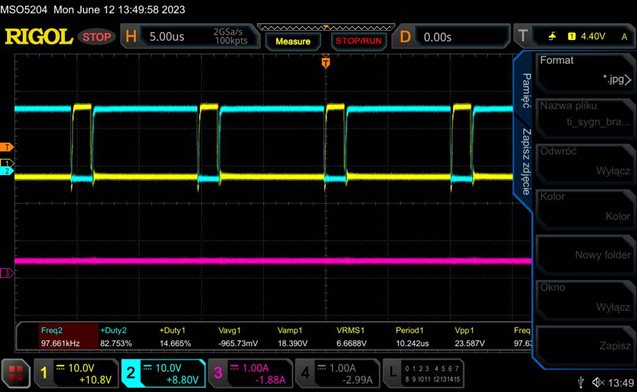
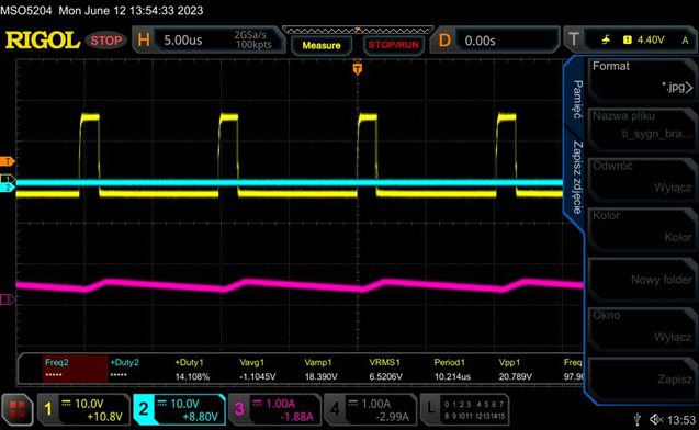
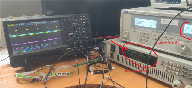
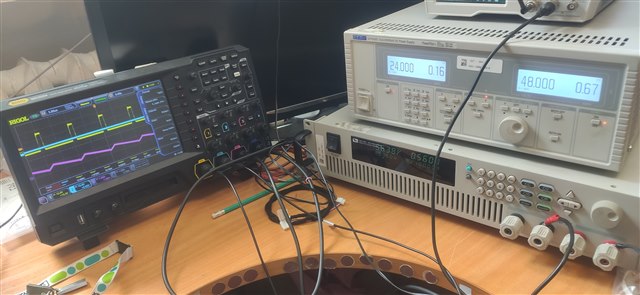
In this case, the output PWMs are about 14% and 83% duty on the first channel. The problem is that I can't change the duty cycle even under load (50 Ohms, 20V in LV). I also noticed that on the COMP1 pin there is ~0.44V at 28% duty and it rapidly increases to ~6.4V at 29% duty. I have attached a schematic with the LM5170-Q1 connections. The current measurement is realized using an HMSR-30SMS LEM sensor.

Kind regards

lm5170_and_current_meas.pdf

  • Hi Lukasz,

    I don't quite understand your question.

    What is the input and output voltage? What is the current?

    You mentioned LM5170-Q1 operates in boost mode, what do you mean by "50 Ohms, 20V in LV"?

    What is 28% and then 29% duty cycle?

    Can you share some waveforms?

    Best Regards,

    Feng

  • Hi Feng,

    the output voltage is not specifically set, and the given input voltage is 20V. The current results from the given output resistance set on the electronic load resistor - 50 Ohms. LV means the input of the step-up circuit (low voltage). Correspondingly, HV means the output of the step-up. I am attaching some pictures and waveforms in the attachments. Photo 1 shows the gate signals on the transistors after starting the control without the converter load.


    The PWM duty cycle applied to the lower transistor is then approximately 14.7%. This cannot be changed by the duty cycle at the ISETD input. After applying 20V to the boost circuit input, the PWM duty cycle of the lower transistor is also at a similar level of about 14%, and this cannot be changed by the duty cycle at ISETD. Photo 2 shows the gate signal of the lower transistor and the inductor current waveform. Blue channel is not connected.


    I increased the input voltage to 48V, and it is still the same - there is no possibility of changing the duty cycle for the transistors. Photos 3 and 4 show the oscilloscope waveforms and the values obtained at the receiver.


    It can be said that the circuit works well, but only at one, unchangeable duty cycle value.

    Best regards,

    Łukasz

  • Hi Lukasz,

    You are configuring the LM5170 to constant current mode. In CCM, the duty cycle will be determined by the input/output voltage ratio.

    Best Regards,

    Feng

  • Could you elaborate on that? Could it be caused by the HV output not being connected to the Vin input as in datasheet?

  • Hi Lukasz,

    Can you tell me what is the input/output voltage and current? What is the load?

    Best Regards,

    Feng

  • Hi Feng,
    Input voltage is in first case 20V, output is 23.4V. Current is 0.46A
    In second case input voltage is 48V, output is 56.38V and current is 0.56A. You can also see this on screens , which i have sent.

    Best regards,

    Łukasz

  • Hi Lukasz,

    In CCM, the duty cycle is determined by the input/output voltage ratio. You can calculate the duty cycle in both cases.

    As 23.4/20=1.17, 56.38/48=1.175, you should have similar duty cycle in both cases.

    Best Regards,

    Feng Ji

  • Hi Feng,
    could you explain how to set the LM5170 to work in a different mode? I would like to set the duty cycle on the output using PWM on the ISETD pin.
    Best regards, Łukasz Maksimowski

  • Hi Lukasz,

    It does not make sense to control the duty cycle directly.

    You want to have a constant voltage operation or constant current operation?

    You may refer to LM5171EVM user guide.

    Best Regards,

    Feng Ji