This thread has been locked.

If you have a related question, please click the "Ask a related question" button in the top right corner. The newly created question will be automatically linked to this question.

UCC21520: Half-Bridge IGBT Driver: Capacitor Selection, Rgs Resistor, SiC Diode Protection, and Power Supply Configuration Queries

Part Number: UCC21520

Tool/software:

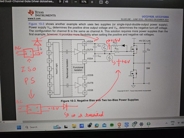
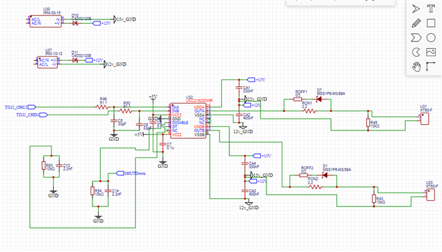
I am using the UCC21520 to drive an IGBT in a half-bridge configuration (SKM100GB12T4 from Semikron). My intention is to apply +15V to turn it on and -12V to turn it off. Based on the datasheet, I believe Figure 10-3 illustrates the appropriate configuration for my application. I have two isolated +15V and +12V supplies on my board.

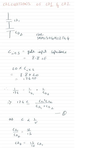
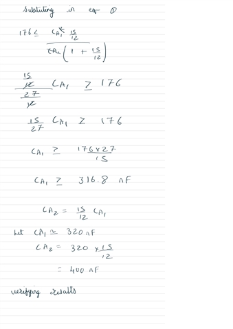
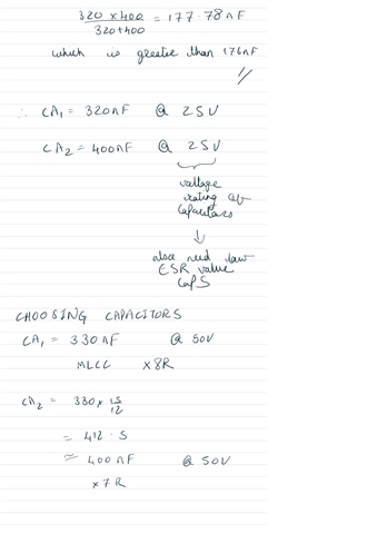
My main concern pertains to the selection of the CA1 and CA2 capacitor values. These values need to be calculated based on the switching frequency (30 kHz) and the gate charge. Could you provide an example of how these values are derived?

Additionally, I have the following queries:

  1. Should I remove the Rgs resistor that is present in the typical application circuit, or can I retain it?
  2. Should I add a 1200-V SiC diode to protect my +15V and +12V supplies from high voltage? Notably, when the high-side switch turns on, the high DC bus voltage is directly applied to the -12V supply.
  3. Can I use the same +15V and +12V supply for both the high and low sides?

Please correct me if there are any misunderstandings in my configuration, as I am still getting acquainted with it. Your guidance on these matters would be greatly appreciated.


  • Hi Suyog,

    Thank you for your interest in our devices!

    Here is a relevant thread that explains this in detail with an example: (+) UCC5350-Q1: Capacitor size choose for Negative Bias curcuit used in SiC mos driving - Power management forum - Power management - TI E2E support forums 

    For your additional questions:

    1. The Rgs resistor is there to mitigate the risk of dV/dt induced turn-on due to miller current. It is not always necessary, but would recommend leaving a socket there in case.
    2. Adding a diode or ferrite bead is common to see to protect the supply.
    3. Yes, with isolated supplies this should not be a problem.

    Please feel free to ask any additional questions below!

    Regards,

    Hiroki

  • Thank you for your response @Hiroki Honda. I have followed the method outlined in the provided link and am now sharing the results with you. Please review them and let me know if there are any errors.


    Additionally, I have a question regarding the voltage rating of the capacitors. In the design, I selected capacitors rated at 50V. Should I instead use capacitors rated for the DC link voltage, which is 600V in my case?

    My design includes two additional drivers with the same configuration. Can I use the same power supply (+15V, +12V) as shown in the attached diagram? While using the same power supply would be cost-effective, I am confused about its implications and functionality within this configuration. A detailed explanation would be greatly appreciated.

    Moreover, it would be very helpful if you could review my design to ensure there are no errors before I proceed with manufacturing.

    Thank you.


  • Hi Suyog,

    These capacitor values should work sufficiently given your load capacitance.

    For these capacitors, 50V rating will be fine since these capacitors will not see the HV bus voltages. 

    Regarding the power supplies, using the same supply for the LS channels would be fine since they share the same ground. However, for the HS channels you would need separate iso supplies because the ground would be a different node for each.

    Taking a look at the schematic you attached, nothing seems to stick out to me as unusual. Please feel free to ask additional questions below if needed!

    Regards,

    Hiroki