This thread has been locked.

If you have a related question, please click the "Ask a related question" button in the top right corner. The newly created question will be automatically linked to this question.

LM51561-Q1: Slope compensation and Soft start

Part Number: LM51561-Q1
Other Parts Discussed in Thread: LM5156

Tool/software:

Hi,

I want to design a boost converter to have a 160V/50W output, max 80W. The input voltage is between 9-30V so I did a flyback design with the LM5156. I attached the SNVC240 calculation tool.

With the Pspice for Ti software, I tried to simulate this design.

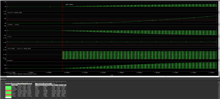
At the start up, the peak primary winding current is more than 50A, after 2ms, the limit current seems to work fine ! 

I don't understand, is it something wrong with the slope compensation and the soft start function. I didn't see any relationship between the SS and comp voltages.

 Please can you explain me this inrush current at the start up ? 

Thanks,

SNVC2402870.LM5155_56_Excel_Quickstart_Calculator_for_Flyback_Regulator_Design.xlsxLM5156-Q1_TRANS.DSN

  • Hi Jerome,

    thanks for reaching out.

    We will look into this and come back with an answer by tomorrow.

    Best regards,

    Moritz

  • Hi Jerome,

    LM5156 is in current limit also at the beginning, but already operates in minimum on-time.

    Cou can use a bigger value for the softstart capacitor, this will help to lower the current at startup.

    Best regards,

    Moritz

  • Hi, increase the soft start capacitor does not change my issue. I changed the Rsense (R12) value to 6 Ohms to have inductor peak current limit at 16.7A.

    I would like to understand : 

    -the condition of the Boost start up (see Figure 9.2 of the datasheet :) : in my simulation, the controller start to drive Vgate when V(CS) >450mV 

    - why the controller doesn't stop when V(CS) is higher than 100mV and the primary inductor current is higher than 50A !

    Is it an issue with the simulation file ?  

    thanks,2047.LM5156-Q1_TRANS.DSN

  • Hi Jerome,

    Lm5156 has a minimum on-time:

    At 1MHz, this will be ~85ns.

    Even when the current limit is exceeded, it can not turn off faster.

    In reality the current can not rise that high in such a short time. This seems to be simulation issue.

    Best regards,

    Moritz

  • OK!

    Is it due to the spice model of the component or due to the simulation tool (Pspice) ?  

  • Hi Jerome,

    I run a simulation with this model and can confirm Moritz reply.

    During the strong current peaks, the device is already switching with minimum on-time, so this is not a issue of the LM5156 model, but of the PSpice simulator.
    It is also important to keep in mind that this testbench uses ideal power supplies and inductors, so inrush currents may be much stronger than in a real application.
    The reason why the inductor current ramps up so fast in the beginning is the combination of small inductance and high output capacitance.
    Low inductance allows for fast ramp up of the inductor current and high output capacitance increases the initial load current to charge the cap.

    Once the initial inrush peak is over, the ramp up curve of Vout becomes steady and peak current limit of 16.7A works properly.

    To make the simulation more realistic, you can add some amount of ESR to both inductors and the power supply.
    This may reduce the current peaks, but will not be enough to fully remove them.

    Best regards,
    Niklas