TPS552882-Q1: Boost Regulator TPS552882QWRPMRQ1

Part Number: TPS552882-Q1
Other Parts Discussed in Thread: TPS552882EVM-2MHZ, TPS552882

Tool/software:

Hi Support team,

I have designed and implemented Boost regulator circuit with TPS552882QWRPMRQ1 and when i given the input as 12V and 3A and generating the output as 19V. Here i am getting the issue at output capacitors.after some time, the output is not getting that too these output capacitors are failing in impedance check. is the problem with Mosfets side or input side?

please help me to resolve.

Thanks and Regards,

Tagore.

  • Hi Tagore,

    Thank you for reaching out. May I know what is the application here? What is the current load?

    Can you provide the schematic so that I can check the design problem. Also please provide part number and datasheet of output capacitor and inductor.

    Regards,

    Mulin

  • Hi Mulin,

    Sorry for this delay,

    PFA

    And my application is to charge the battery with 12V,6A input, to generate 18.8V,6A  and communicate with SMBus to control the charging.

    Regards,

    Tagore.

    4S6P BATTERY CHARGER (100W)_V0.1_SCH.pdf

  • Hi Tagore,

    From schematic I didn't see obvious concern. Make sure C3 effective capacitance is larger than 2uF with 5V DC bias. Recommend to add RC snubber in SW 1 and SW2.

    What is the load current when you do the test?

    Can you help provide Vin Vout SW1 SW2 inductor current waveforms? It will be good to capture output failure moment. I want to check device working performance.

    Regards,

    Mulin

  • Hi Mulin,

    Yes C3 is 4.7uF and i did not added RC snubber in SW1 and SW2 due to my part is damaged.

    1. Can i get these Vin Vout SW1 SW2 responses from your side so that i can verify my self after getting my part shipment.

    2. when i saw your design for TPS552882EVM-2MHz,it is designed for 2.7V - 36V as input and 22V/3A. But my input is 12V with 6A and output is 18.8V with 6A. can i get this exact with this design

    3.From my charger IC BQ25720RSNR,not getting the output voltage.i verified the voltages at MOSFET (Q7) getting 18.8V at pin 5,6,7,8 and at pins 1,2,3 voltage is 0.

    4.When i tried to communicate with MCU(PIC16F18046-E/ML)  the boost IC i.e, TPS552882QWRPMRQ1 is damaged.2364.4S6P BATTERY CHARGER (100W)_V0.1_SCH.pdf

    Can you help in this to resolve.

    Thanks and regards,

    Tagore.

  • Hi Tagore,

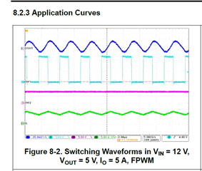
    1. Please refer to 8.2.3 in datasheet. Please provide the waveforms when your part is ready.

    2. TPS552882 can support 18.8V/6A output with 12V input voltage. But the input current should be around 18.8*6/0.9/12=10.4A. 6A input current is not enough. Also, in this power, recommend to use 400kHz switching frequency and 4.7uH inductor. Set R6=49.9k and L1=4.7uH. Set R5=26.4k to get 12.5A inductor current limit.

    3.What is working condition when you did the test?

    Regards,

    Mulin

  • Hi Mulin,

    Thanks for your support,i will do these changes after getting the part.

    Please clarify about the poin 3 and 4.?

    And do i need program to get the output without MCU at charger IC side?

    Regards,

    Tagore.

  • Hi Tagore,

    About point 3, recommend to raise a new thread about BQ25720RSNR. This thread can not be assigned to two product line at the same time.

    About point 4, do you mean PG and CC function? TPS552882 is not controlled by MCU.

    Regards,

    Mulin

  • When i giving the 12V/200 mA it is working fine but after increasing the current to 3A it is getting short,

  • Hi Tagore,

    Please help provide the Vin Vout SW1 SW2 inductor current waveforms? It will be good to capture output failure moment.

    Please change R6 to 49.9k and L1 to 4.7uH for thermal consideration.

    Can you provide layout file of TPS552882Q? I want to check if there is any layout issue.

    Regards,

    Mulin