TPS543C20A: Switcher design assistance using TI calculator tool

Part Number: TPS543C20A

Tool/software:

Hello,

I am working on designing a power supply with the TPS543C20A. 

I will be using the TPS543C20A to step 14V Vin down to 1.35V Vout @ 25.5A Max Iout.

I don't have very many hard design parameters outside of that. I'd like a small enough ripple so that I don't see any switching artifacts on the output of the LDOs that the TPS543C20A will be providing the 1.35V to. These LDOS will be regulating the 1.35V to 1.2V.

As you can see by my provided information, I am by no means a power expert.

I've been working with the provided design calculator for the TPS543C20A. 

The first thing I've noticed is when I type in all of my parameters, the COUT values generated trigger a design caution:   


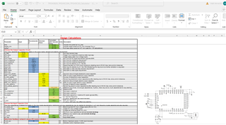
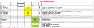
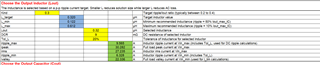
It looks like the tool is warning about too much output capacitance causing loop instability.

I began with the provided value but the undershoot and overshoot vout cells went red. There doesn't seem to be a value that will turn the COUT cell green. 

I was wondering if the TI team could sort of guide me through properly using the calculator as I don't have much(if any) design intuition on what the different values in the tool should be and am lacking most of the stricter requirement information that the tool allows you to design for and I would like to make sure I'm using sensible values at the least.

Any help that TI Engineers could provide would be greatly appreciated.

Thank you,

Matt

  • Hi Matt,

    Happy to help guide you through this design! As a starting point, would you be able to share your excel file here? I will make some tweaks to that, with a focus on low output ripple, and offer detailed explanations for each of the selections

    Best regards,

    Britton

  • Hi Britton,

    Of course. Note I didn't actually calculate a COUT value so the 1500uF there at the moment was just a value I entered when I was messing around with the tool. 

    Thank you so much for your help. Here is the file:

    3683.TPS543B20_TPS543C20A_TPS543C20_Calculator.xlsx

  • Hi Matt, 

    Attached below is the updated excel file with my recommended component selections. I'll explain the design choices that were made as well:

    1. Switching Frequency - Your selection of 1400kHz is a reasonable selection. This "high" switching frequency will allow you to achieve ripple requirements with a lower inductance and less output capacitance, which will ultimately reduce BOM costs. We categorize 500kHz as a middle ground frequency that balances solution size and efficiency, if you do not have strict efficiency requirements then I recommend the1400kHz selection for the above reasons.

    2. MODE - Enabling the API/BB with a mode resistor is by no means a requirement, but it does offer marginal improvements during a load transient. We typically enable API/BB when load transient requirements are strict. In your case, you can enable the API/BB feature or ignore it by leaving the pin open, either solution is perfectly fine. 

    3. Inductor - I noticed that you had a 1uH inductor filled in originally, I believe this was a source of some the issues/design warnings that you were seeing. I adjusted the inductor value to 0.1uH to match the target recommended inductor value for this application, which is designed to achieve a recommended 30% inductor ripple. The selection of 1uH is not possible for this application because the inductor ripple would be so low that the device can not properly sense current. I recommend the 0.1uH selection, but anything from 50nH - 200nH is acceptable. 

    4. Output Capacitors - I went ahead adjusted the output capacitor selection to reduce ripple as low as possible while maintaining stability. In this case, I chose 2x 330uF Bulk Capacitors + 6x 100uF ceramic capacitors. The 330uF bulk capacitors are not a hard requirement, but they allow us to achieve higher capacitance with a lower solution size. Ultimately, you are in the green if you have less than ~1300uF. There is a design caution on the feed forward capacitor, this is not cause for alarm and we always recommend to have a placeholder for the feed forward capacitor & resistor in parallel with the top resistor in the feedback divider. 

    When you design your schematic and layout, feel free to share them with me and I can double check the design before the boards are built! There are schematic and layout guidelines that you can find on a separate tab in the attached excel tool.

    3683.TPS543B20_TPS543C20A_TPS543C20_Calculator_TI.xlsx

    Best regards!

    Britton