TPS23754EVM-420: TPS23730

Part Number: TPS23754EVM-420
Other Parts Discussed in Thread: TPS23754

Tool/software:

Hi 
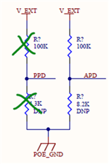
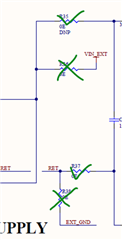
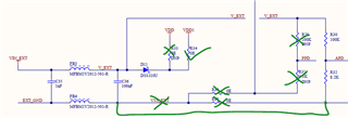
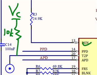
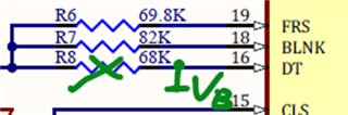
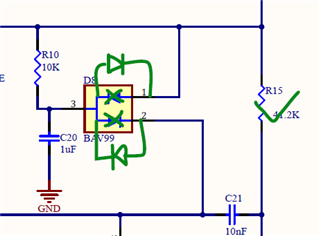
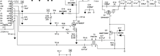
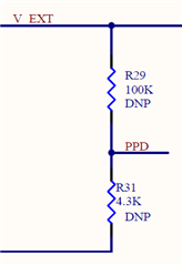
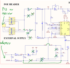
Please verfy the schematics and also the oring section .please provide the step to set priority for the Poe than the external power supply.
Pleas find the schmatics on this link. 
https://drive.google.com/file/d/1UOiTpN14wk_c2hwtcwUv8SlG2utezA1H/view?usp=sharing.

  • Hi Rony,

    Thanks for reaching out!

    I could see there is some grounding issues. Please make VSS and RTN not shorted in the circuit. You can refer PMP6672 "https://www.ti.com/tool/PMP6672" which is a TPS23754 based 5V/5A flyback converter ground connection.

    Besides, I would recommend to only use APD but not use PPD. You can leave PPD pin open to disable it. And PPD refers to VSS instead of RTN. Then if you have an adapter and make the voltage divider rise above APD's threshold, your PD's internal hotswap will be turned off and your adapter will have a higher priority. 

    Please kindly update your schematic and share the updated schematic. Thanks.

    Best regards,

    Diang 

  • Hi
    I am reattaching the poe schematic please verify and share comment on it

    PoE Box.pdf

  • Hi Rony,

    Thanks for your updates. Please see the comments below:

    1. It is recommended to use APD to set the adapter priority.


    2. T2P is an open drain pin which needs to be pulled up by a resistor.


    3. Please tie DT to VB when not using GAT2.


    4. D8’s direction needs to be changed.

    Best regards,

    Diang

  • Hi Diang
    Thank you for great review. Implemented the changes that where recomended and sharing th schematics .We planning to test out the circuit using dc supply and POE. Is it possible to test the circuit using the dc supply by using the APD configration that our idea we are planing to implement.05 Power Supply - Copy.pdf

  • Hi Diang
    Just curious about the role of gate2 pin and how it work and role transformer T3 .Is there any reference document for understanding the circuit

  • Hi Rony,

    Thanks for your update. I will recheck your schematic and get back by this week.

    Best regards,

    Diang

  • Hi Rony,

    Thanks for your patience. May I know what is input voltage for your passive PoE before review the schematic?

    If the passive PSE voltage is higher than 37.5V (higher than the 36.1V adding 2x0.7Vdiodes forward drops), then you do not need to use PPD pin. The passive PSE can directly let the PD turn on without handshake.


    If the your passive PoE voltage is lower than 37.5V, then PPD pin is needed. In this case, a voltage divider between VDD-VSS is needed to set the PPD pin higher than 1.55V when passive PSE is injected. 

    In your case, your PPD trigger voltage is 1.55V/4.3k*(100k+4.3k) = 37.6V, which is not common for passive PSE application. If your passive PSE voltage is something like 24V, 36V, ..., you may need make R31 higher than 4.3k to ensure the PD can turn on at a low voltage. 

    Best regards,

    Diang

  • Hi Rony,

    GAT2 has the same phase with GATE but with a deadtime. The purpose of GAT2 is mainly for driving an active clamping FET on the primary side, or driving a sync FET on the secondary side. And in the schematic you attached, it is for driving a sync FET on the secondary side.

    In many flyback designs, these is no need to use GAT2. 

    Best regards,

    Diang

  • Hi Diang
    Yes our passive PSE voltage is higher than 37.5V .We planing to provide an input volatge of 48v to 56v same as poe voltage range.

  • Hi Rony,

    Thanks for your helpful information. I will take a look on your schematic with this information. Will get back to you in 3 business days.

    Best regards,

    Diang

  • Hi Rony,

    Thanks for your patience. 

    Since your PSE injector is above 37.5V, I would just set PPD open. And I would have PoE injector and PSE both on the RJ45 port. The DC adapter (normally need 24 - 57V) is for the external side. When one of these three is connected, you can have the flyback work.

    Best regards,

    Diang 

  • Hi Rony,

    Since we did not see your reply for a long time, I will close this thread for now. Please reply or open a new thread if you have further questions.

    Best regards,

    Diang