- Ask a related questionWhat is a related question?A related question is a question created from another question. When the related question is created, it will be automatically linked to the original question.
This thread has been locked.
If you have a related question, please click the "Ask a related question" button in the top right corner. The newly created question will be automatically linked to this question.
Tool/software:

Hello,
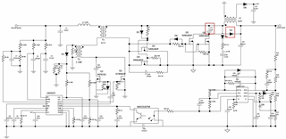
may I ask why adding these two components to the LM5025A caused the output voltage to rise from 5V to 7.5V and to increase along with the input voltage?
Ex:When the input voltage is 36V, the output voltage is 7.5V, and when the input voltage is 45V, the output voltage rises to 10V.
My circuit specifications are as follows:
Hi,
You need to measure the voltage of C17 - its voltage is limiting Q5 and Q6 freewheeling so to cause output inductor energy to flow through D5 from C17 as well then causing higher output voltage. You also need to check your feedback loop - it looks it becomes saturation not able to reduce duty cycle.
C17 is basically making your secondary side like a peak charge so higher Vin peak charge higher to cause higher Vout. You may increase C17 to help resolve along with feedback loop adjustment.
I suggest you talk to the original inventor of this circuit to get help. We are not familiar this circuit so may not provide good advise.
HI,
Thank you for your response.
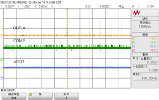
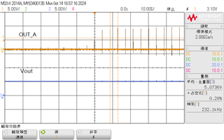
I followed your instructions, and I was able to achieve the desired output voltage. However, the PWM signals from the IC's out_A and out_B are not functioning properly. This occurred with Vin: 48V, Vout: 5V, 230kHz, and Iout:0A.
The circuit's inventor has not responded to me :(.


Hi,
I think the same reason. The capacitor causes the secondary side to the similar to a diode so in peak charge so the pulse width becomes so small and has to be with 0 duty cycle due to the output voltage already in regulation towards over.
Hi,
As it is a peak charge, the feedback loop cannot help much due to the duty cycle cannot be adjusted further smaller so the duty would have to be zero or skip the pulses.