This thread has been locked.

If you have a related question, please click the "Ask a related question" button in the top right corner. The newly created question will be automatically linked to this question.

LP2951EVM: Output Capacitor and Resistor Configuration

Part Number: LP2951EVM

Tool/software:

Hi team

1. Why do output capacitor (C4~C6) and resistor (R7) connected in series then connect another capacitor (C7) in parallel, could you please explain why we adopt this topology here?  And could u please explain the function of C4~C6, R7 and C7? Thanks.
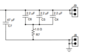
 (LP2951EVM output)

2. Why is C4~C6 (total 6.6uF) connecting R7 in series, or why is it a small capacitor series resistor?  Our customer is using a large capacitor to connect the resistors in series, and a small capacitor connect in parallel. Is this reasonable?  Do you have any insight why they are using different configuration?

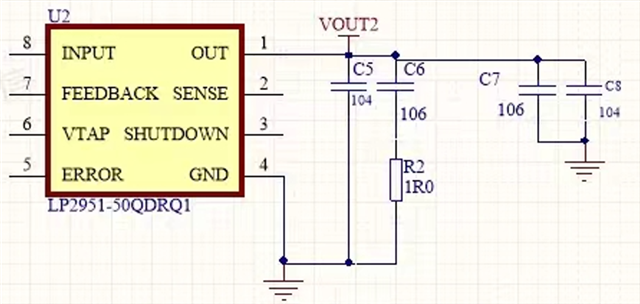
  (Customer's schematic)

Thanks so much.
  

  • Hello Jenny,

    1. The capacitors C4-C6 are connected in series with resistor R7 because of two reasons: a) Often times it is required to add additional output capacitance in steps for various test cases and adding capacitors in parallel reduces the effective ESR of the output capacitor. So, to compare with a single larger capacitor with larger ESR, an additional resistor is added in series. The 1Ω value is for reference and the customer may add any value of R in 0805 size. b) The Cout ESR range for the legacy chip is 30mΩ - 5Ω. R7 may be needed to meet this range depending on C4-C6 chosen and also to explore any specific test cases where ESR has to be varied. 

    C7 is an aluminum film capacitor and gives the customer the option to evaluate these types of output capacitors if they so choose. Please understand that this is an evaluation module, so not all of these capacitors are required to be populated. The customer can populate capacitors specific to their use/ test case (as long as they meet the Cout and Cout's ESR requirements. Some test cases may require evaluating outside of these ranges as well). The EVM provides these options so that customers have flexibility of evaluating all these options on one board itself.

    2. I believe the above answer applies to this question too. I cannot tell why this specific configuration is chosen without knowing the size, type and ratings of capacitors C5-C8. Is this configuration for test or final assembly? And is this question raised by the customer or is this coming from you?

    Best regards

    Ishaan

  • Hi Ishaan, 
    Thanks so much for your kind reply. I'd like to share with you some of my thoughts and we can have some discussion.
    1. Are C4~C6 used for filtering? And R7 is for ESR, C7 depends on specific design?

    2.the parameter in Customer's configuration: C5=100nF, C6=10uF, C7=10uF, C8=100nF. (C5&C6 are Cout, C7&C8 are Cload), R2=1ohm.

    While ignoring the load capacitor, if C6 (10uF) connect to R2 (1ohm) in series, then connect to C5 (100nF) in parallel, will Cout still satisfy >1uF?  How can I prove customer that the loop is stable. Customer totally gave me three schematics to discuss the loop stability. Thanks

    Best Regards, 

    Jenny Ou

  • 1. C4-C7 are at the output so they are not used for filtering for this specific case. R7 is for ESR like you mentioned and C7 is also an output capacitor to be added as required. Just a different type and form factor of capacitor. Please refer to this app note for a clearer understanding of this topic: https://www.ti.com/lit/ta/sszt654/sszt654.pdf?ts=1729663221823&ref_url=https%253A%252F%252Fwww.bing.com%252F

    2. What you have provided above are capacitor values, not types and ratings. It is difficult to ascertain whether the solution is stable without knowing these details. Assuming the ratings satisfy the Cout range criteria, then the arrangement will lie within the recommended range for Cout. If the LD GND and the Ground for C7 and C8 are the same, then the total output capacitance is C5+C6+C7+C8