This thread has been locked.

If you have a related question, please click the "Ask a related question" button in the top right corner. The newly created question will be automatically linked to this question.

LMR64010 Inrush/Soft-Start

Other Parts Discussed in Thread: LMR64010, TPS62111-EP, TPS62112-EP, TPS62112

Hello,

I am having trouble with a PDS I am designing using LRM64010 (and other switching DC/DC's).  I've attached a webench design report which is pretty close to what I am using.  I purchased the LMR64010 demo board and replaced the following components:

D1 -> MBR0530T1G

C1-> 10uF MLCC

CF - > 82pF C0G MLCC

C2 -> 10uF MLCC

R1 -> 246k Resistor

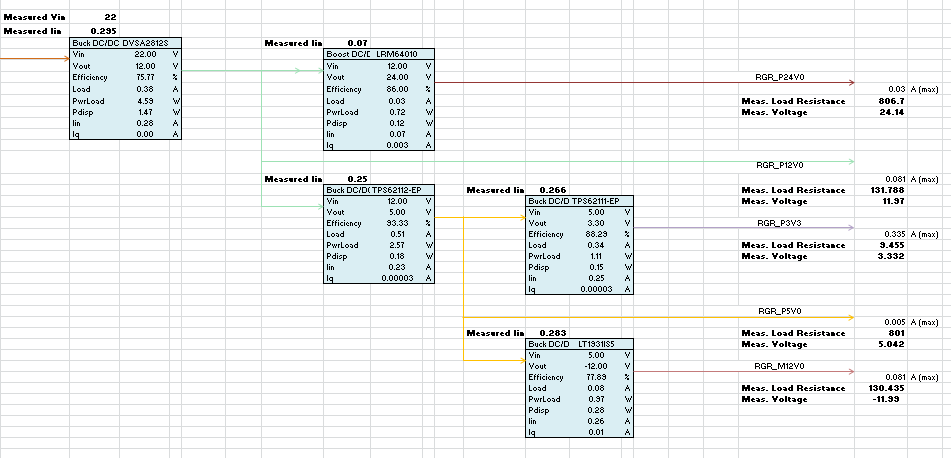
Vin: 12V, Vout: 24, Io = .030A

I load the output of the circuit with a resistor of approximately 800ohms for .030A of output current.  Using a bench supply and the loaded circuit standalone I see an input current of .07A. There are other loads on my 12V input rail totaling around 331mA.  Adding in the load from the 24V rail I should have about 401mA of load current.  My 12V rail has a max current limit of .5A, I use a bench supply for this at the moment but in the final design this is a seperate DC/DC. 

What I see when I attempt to power up the entire PDS is that if my current limit is set to .5A I OC the supply.  While the supply is in OC protection I can probe each of my voltage rails and all are fine except for the LMR64010 rail which is pulled down.  If I set the current limit on my supply to around 1.1A or above the entire PDS powers up fine with a current draw of around 400mA. 

What I suspect is happening is the inrush current from the network of DC/DC's is exceeding the .5A limit and preventing the LMR64010 from powering up properly.  The problem I am having is trying to figure out what inrush current too expect, and how to properly size my 12V rail.  I am trying to determine if there is a way to control the inrush current of the LMR64010.  I am using other DC/DC's in the PDS such as TPS62112-EP and TPS62111-EP but their datasheet mention that they limit inrush current and they do not seem to be what is driving the overcurrent. 

design.pdf
  • Hi Patrick,

    One thing to be careful of when using a non-synchronous boost is that when the device is not yet running there is still a short from Vin to Vout through the inductor and diode. So when your 12V rail starts up it is charging all of the cap on the 12V and 24V rail and the current will be cdv/dt.  Depending on the rest of your design this might be enough to trigger the current limit.

    If this is the issue you could try slowing down the 12v startup.

    Let me know if this helped, if not I can help look for other possible causes.

    Marc

  • Thanks for the response Marc.  Unfortunately I am using a MIL hybrid isolation DC/DC as my 12V rail and I do not have a way that I am aware to slow its turn on.  To be fair the bench power supply I am using with a current limit set to .5 to replicate the DC/DC may not have the same turn on time so it is likely worth my while to put the actual DC/DC back in the loop to test the response.  Another thing I did fail to take into consideration was the cdv/dt.  I am using two non-synchronous DC/DC's in my design so I may revisit the amount of capacitance I place across the rails to see if I can save some current there.  What confuses and worries me about the symptom is that it does not eventually recover.  If the load from other circuits on the rail are .331A and my current limit is .5A I would think that eventually there would be enough headroom for the 24DC/DC to turn on. 

    I've attached a picture of my dc/dc network.  I am generating 5VDC from the 12V rail using the synchronous buck converter TPS62112.  I am expecting that if I move the 24V rail to be powered from the 5V rail (at the cost of efficiency) and use the PG pin from the 5V converter to turn on the 24V converter that it may allieviate some of the inrush (assuming the cdv/dt current while the device is off doesn't kill me).  Just wondering if you see any pitfalls in this philosophy or have any other thoughts. 

    Thanks for the help. 

  • Hi Patrick,

    Moving the boost to the 5V rail will increase the 12V current another 70mA.  This might exacerbate your problem.

    However, maybe delaying the startup of the LMR64010 device by using the 5V rail PG as an enable will improve the start up.

    Quick question.

    1) When the input supply is current limited what is the voltage on the 12V rail?

    Regards,

    Marc

  • I agree that it will increase the overall load of the 12V rail but I guess I was hoping that since the TPS61112 has internal soft start up it may mitigate the problem.  Originally I was hesitant to use the PG from the 5V rail to enable the 24V rail because I would not want a malfunction on the 5V rail to impact the 24V rail.  Secondly since the load on the 5V rail has such a significant portion of the overall load I would  expect that to further limit the headroom when the 24V rail attempts to come up.  I brought the input and output capacitance down from 10uF to 4.7uF and it seems to have improved my inrush issue, I fear I am not giving myself enough margin though so I would like to see what I can do to further improve.  Both the 5.0 and 3.3V rails have two 22uF of output capacitance each (per the recommended application on the datasheets) which is likely a significant contributor to inrush.  Also I added a slow start on my inverter which helped as well. 

    To answer your question, when the input supply is current limited the voltage on the 12V rail is fine, along with all other rails, usually right on or near 12V.  The 24V rail seems to be the only one that suffers.

    Since I originally posted I did a little bit of work with some current probes and I can see that the output of the DC/DC converter goes beyond .5A, I've seen as much as 1.25A for a few mS, so I do not think it is the DC/DC hard capping, at least not at .5A.  Also, when the actual DC/DC is powering the 12V rail (being powered by a bench supply @22V) the supply doesn't actually trigger OC.  What I see is my overall network is pulling low current, and when I probe the rails I see that 24V isn't up.  When I replace the 12V DC/DC with the bench supply directly I am able to reproduce the symptom of the 24V rail not coming up when I set the current limit too low. (but higher than the nominal load of .4A). 

    I am sure that using the bench supply with a current limit isn't really the best way to go about trying to figure out the problem, I am simply not sure what is actually happening at the moment or how to try to go about debugging.  Thanks for the feedback so far on this issue.

  • Hi Patrick,

    My only current thought is that perhaps the part is getting stuck as it turns on before the 12V rail is established.

    Can you try the test of Enabling the part with the 5V supply PG?  If this works then perhaps the part is just trying to turn on at too low a voltage and getting stuck.  I will look for a demoboard and see if I can recreate this.

    If this is the problem, then we can add an under voltage lockout to the Enable pin using a zener.

    Regards,

    Marc

  • Makes sense.  I wouldn't really have guessed this to be the issue because it seemed to be related to the current limit setting on the power supply.  I wonder if the current limit is stifling the turn on of the 12V rail which then affects the turn on of the 24V supply.  I can look into what you are suggesting.  I'll use a scope to monitor the rails to see what is going on when the limit is set and when it is not set and upload.

    EDIT:  K so I went to the lab and looked at it again.  First of all I was incorrect when I said only the 24V rail was failing.  When the overcurrent occurs on the bench supply all the rails are at lower voltages.  It seems to be directly related to the actual current limit of the supply, the higher the limit the closer the rails are to max.  When I use the PG pin from the 5V rail to enable the 24V rail I can power up the entire network with even less of a current limit, around .35A.  I was also wrong when I said the current limit doesn't trigger when I power the 12V dc/dc off the bench supply, it does.  But at this point it is fairly obvious that the bench is triggering on the inrush current into the 12V dc/dc and causing all the supplies to fail to come up.  Since in my final application the bus is powered off a battery with essentially no current limit I am not concerned with this issue.

    I've gone back and forward with what I've described because I was actually seeing two separate issues.  The first issue was what I just described and is simply because my current limit was set too low.  The other issue happens when I do not soft start my inverter circuit which is a LT IC.  When that happens the bench supply doesn't limit it just pulls lower than expected current.  The 12V rail looks bad like its failing to regulate.  The inverter is powered off the 5V rail which is a TPS61112 so I am wondering if it has to do with the LT trying to come up too fast and getting stuck in a similar way you described in your last response.  Either way I will need to go back and more closely review the TPS61112 datasheet and the LT part to see if I am missing something obvious.  I think for the sake of the issue in this thread my problem is solved.