This thread has been locked.

If you have a related question, please click the "Ask a related question" button in the top right corner. The newly created question will be automatically linked to this question.

BQ24095 Schematic Revew

Other Parts Discussed in Thread: BQ24095, BQ24095EVM-005, BQ24090

Hello,

Could you review attached schematic and let me get the result?

And there are some question

1. If there is any problem when it booting without Battery?

2. When 1A charging current is used, is there any thermal issue?

Please let me get your reply ASAP.

Regards,

NickyAR5800 Rev D_20160819_BQ24095 charger.pdf 

  • To answer your questions,

    1. When no battery connected, the load can still be powered from OUT pin. However, battery detection routine runs at OUT meaning the voltage at OUT pin is a square waveform looks like in figure 23 in the datasheet.

    2. Thermal performance varies largely on layout. You can use the thermal information and calculation in the datasheet to estimate the thermal performance. However, the thermal model in the datasheet are specified under specific board condition (all information can be found in the datasheet). Please also follow the layout guidelines in the datasheet as well for optimal thermal performance.

    The schematic looks ok. Please make sure ISET2 is pulled to the desired state. If ISET2 is been pulled high which sets the input current limit to 500mA, then the charge current will  not reach 1A.

  • Hi Jing Zou,

    Thank you for your kind answer.

    I have additional question about number 1.
    You mean square waveform looks like in Figure 22, not 23. Am I right?
    And How can I make battery detection routine do not run at OUT, when no battery connected?

    Please let me get your answer ASAP.

    Regards,
    Nicky
  • Yes. Figure 22.

    The battery detection routine cannot be disabled. 

  • Hi Jing Zou,

    Thank you for your quick reponse.

    I have additional question about BQ24095.
    1. What is the difference between Vout and Vo(reg) in datasheet?
    2. Why Recharge is tested with Vout=4.25V not 4.2V or 4.35V? (Page. 8)
    3. About Battery detection routine, could you let me explain it easily. I cannot understand Figure 20. Battery Detect Routine because of confusion between Vout & Vreg.
    And if fully charged battery is disconnected by external FET, how can it be recognized during Battery Detect Routine?

    Sorry for bothering you with some basic questions, but please let me get your answer.

    Regards,
    Nicky
  • 1. VOUT is the voltage on OUT pin. Vo(reg) is the battery regulation voltage (fully charged voltage).

    2. VRCH is the recharge threshold. After battery is fully charged (4.35V for bq24095), when the battery voltage is discharged to ~100mV below VO(REG), charging restarts. Thus your test result is 4.25V.

    3. Please see figure 20 for battery detection routine flow. 

    •Battery detection routine turns on after power up
    •VREG is default to 4.2V
    •Once battery detection turns on, a 25ms timer is on.
    •At the end of the 25-ms timer, the IC checks if the voltage on OUT pin is lower than 4.1V (VO(REG)-100mV).
    •If the OUT pin voltage seen by the IC is higher than 4.1V, then the battery detection routine moves on the phase 2.
    •Once the IC determines that VOUT is higher than 4.1V, the IC sets VREG to 3.8V (VO(REG)-400mV).
    •IC starts 25-ms timer
    •At the end of the 25-ms timer, VREG returns to 4.2V, and the IC checks if VOUT is higher than 3.9V (VO(REG)-300mV).
    If yes, then battery preseent, IC exits battery detection routine.

    If the battery is disconnected to the OUT pin, then it will not be able to detect the battery.

  • Correction:

    •Battery detection routine turns on after power up
    •VREG is default to 4.35V on bq24095
    •Once battery detection turns on, a 25ms timer is on.
    •At the end of the 25-ms timer, the IC checks if the voltage on OUT pin is lower than 4.25V (VO(REG)-100mV).
    •If the OUT pin voltage seen by the IC is higher than 4.25V, then the battery detection routine moves on the phase 2.
    •Once the IC determines that VOUT is higher than 4.25V, the IC sets VREG to 3.95V (VO(REG)-400mV).
    •IC starts 25-ms timer
    •At the end of the 25-ms timer, VREG returns to 4.35V, and the IC checks if VOUT is higher than 4.05V (VO(REG)-300mV).
    If yes, then battery preseent, IC exits battery detection routine.
  • Hi Jing Zou,

    Customer tested their board and BQ24095EVM-005, asked about below 2 issues.

    1) After Booting without Battery, if current consumption is over 500mA, there is no Vout.
    - Booting by Adaptor 5V power without Battery.
    - ISET2  ==> Low = ISET
    - ISET ==> 560Ω = 1A
    - TS ==> 10KΩ pull down
    - Booting by Adaptor 5V power without Battery, there is Vout at first..
    - After system booting and current consumption is over 500mA, Vout doesn’t come out any more.
    - Does it normal operation of BQ24095?
     
    2) During Battery Charging,  Charge current decreased in  Constant Current Mode.
    - Low Battery(3V) connect, and test charging.
    - Battery capacity = 2600mAh
    - ISET2  ==> Low = ISET
    - ISET ==> 560Ω = 1A
    - PRE-TERM ==> 4K = 200mA(Termination Current)
    - TS ==> 10KΩ pull down  
    - During Battery charging, Current decreased under ISET setting in CC Mode.
    - 1A charging about to 3.9V, but Battery voltage goes up, current goes down.
    - Refer test result in next slide. (Test both of customer board & EVM, the result is the same.)
    - Does it normal operation of BQ24095 during 1A charging?
    Please refer attached for more detail information, and let me get your answer ASAP.
    Regards,
    Nicky
  • Regarding 1, what is your adpater's power rating? Can you try with the power supply and set current limit to > 500mA? 

    What kind of system load do you have?

    What is the slew rate at start up?

    BQ24090 is a linear charger which is essentially like a LDO. If the load is powering up without a battery, we suggest to increase the output capacitance for larger load step.

    Regarding 2, where is the battery voltage measured? how is the battery connected? Assuming using long cable or wires to connect the battery to the board, 1A * 0.5ohm = 0.5V, there can be 0.5V drop from OUT pin of the IC to the battery. If you try to measure the voltage at IC OUT pin, then you should see the voltage is regulated at close to 4.2V where the charging enters CV mode. Please make sure there is as little drop from battery to the OUT pin as possible.

  • Hi Jing Zou,

    Regarding 1. Customer tested with BQ24095EVM-005.
    She used Power supply voltage 5V and current limit 10A for input power source. And Vout connected to Electric load device for only current load.
    - ISET2 ==> Low = ISET
    - ISET ==> 560Ω = 1A
    If BQ24095 can have Vout with over 500mA load, could you test it with EVM and let me get test result.

    Regarding 2. If you have BQ24095 1A charging Test result, could you provide this test result?

    Regards,
    Nicky
  • Regarding 1, not sure if i have mentioned before, if the application requires power on the load without the battery, we do recommend using a charger with power path function for more stable system output. 

    Can the customer try a different power supply? Some power supply does not respond well with load transients. I am using Agilent E3631 and was able to supply >500mA electronic load at OUT. 

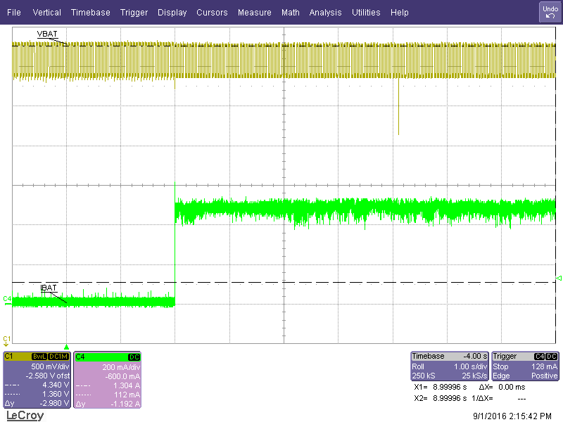
    As you can see from the scope capture, since the OUT pin is performing battery detection, the voltage is oscillating between 4.35V and 3.95V. This casuses a lot of noise and oscillation on the output current pulling from the electronics load as well.  

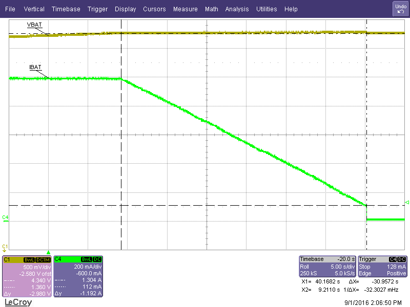
    Regarding 2, I have one correction regarding on my last post, for bq24095, the charge current should start tapering when the voltage on OUT pin is around 4.35V. Have you tried measuring the voltage at the IC OUT pin during charge cycle. 

    Below is a scope capture on when I use a battery simulator and increase the voltage by 1mV per step. As you can see the VBAT (Voltage measured on OUT terminal on the EVM) is around 4.34V when the charge current start to reduce.