This thread has been locked.

If you have a related question, please click the "Ask a related question" button in the top right corner. The newly created question will be automatically linked to this question.

WEBENCH® Tools/UCC28740: UCC28740

Part Number: UCC28740
Other Parts Discussed in Thread: TL431, UCC28710

Tool/software: WEBENCH® Design Tools

Good morning, 

I need to do a AC/DC from AC line to 24V DC. I implemented the design from Webench directly changing some "custom made" components for some comercial ones (the transformer and the optocoupler). In the secondary side it is supposed to have 24V DC and I get only from 6 to 12V.

I have tried to the change the Rcs, the Rtl, etc. and still not finding a solution. 

I attach the difference of the transformer custom made and the comercial:

Parameter Custom made Commercial
Npri 109 1
Nsec 22 0.188
Naux 17 0.156
Lp 1.57mH 560 uH

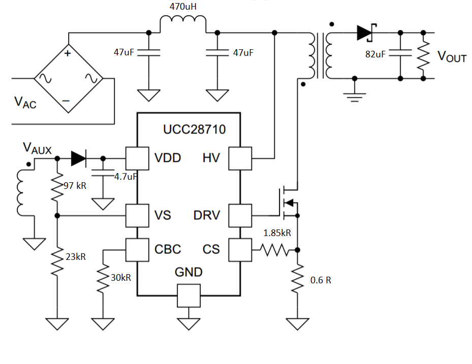
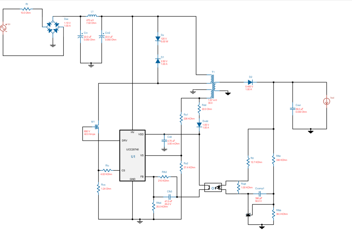
I attach too the schematic of the system: 

I am testing without load, as I have seen in the datasheet that it would have the output voltage even thought there is no load. 

I would be grateful if somebody could help me please. 

Best regards to everyone, 

Guifré

DTU student

  • Guifre,

    Can you clarify the following for me:

    Firstly, can you confirm some spec details:
    - What is the AC input range min to max (i.e. is this wide input range AC, or low-lien only, or high-line only)?
    - What is the max required load current?


    I take it that you first made a paper design in Webench, did that design

    You say that you implemented the design from Webench, do you mean that you designed a PCB and built some hardware based on the Webench paper design?

    In doing so, you changed to a different transformer and opto, but only get 6-12 V output from the hardware?

    I see that the turns ratios are a little different, that will have some impact, but should be ok for initial testing. However, the transformer inductance is substantially different from the original design, this will limit the power to ~33% of the original Webench design. Also depending on the size and actual Np of the transformer used, it may be saturating.

    You should check the Bpk of your actual transformer to make sure it will not saturate.


    You should check the secondary side opto/TL431 to make sure the feedback polarity is correct, and all values are correct. Check the cathode of the TL431 to make sure that it has enough headroom. Depending on the opto CTR, the TL431 does not need to sink very much current. Max FB current of the UCC28740 is 30 uA, even with 10% CTR that’s only 300 uA on the emitter side of the opto, which would only drop ~4 V on the 12k7 resistor that feeds the TL431. Check that all resistor values in the secondary feedback circuit are correct and that all components are correctly soldered.

    Is the power supply attempting to regulate low, or is it running in a burst mode, or with erratic switching behaviour?

    What happens when you increase the load?


    If you can give more information, waveforms, etc then we can try to help you.

    Thanks,
    Bernard
  • Hello Bernard,

    First of all thanks for the fast reply.

    The AC voltage range in the input is 110-230 VAC. And the maximum current output would be arround 2 Amps.

    And yes, I did it in the webench and design a PCB out of the paper design on the webench.

    The transformer claims for a 66W output, so I think it would not have to saturate. I attach the datasheet from the manufacturer. 

    For the TL431 what do you mean if I have enough headroom? If all the resistors from webench are the ones installed, I should review the calculations?

    The CTR for my optocoupler is within the interval 130%-260%.

    Making some captures with the oscilloscope I have seen that the controller is only doing the startup sequence, only 3 cycles and then is repeating these 3 cycles every 1 second more or less. I think thats because in the CS pin, the maximum allowed voltage is 1.5 and I am getting almost 2 V, producing a OC fault. Do you think it could be the cause? 

    Looking forward to your response, 

    Best regards, 

    Guifré ka5038.pdf

  • Guifre,

    First of all, for that power level (48 W), the original transformer inductance of 1.57 mH does not sound correct - that's far too high for such a high power level. In fact, even the value of 560 uH that you actually used sounds too high. Did you input the correct load current in the Webench parameters when you generated the design?

    I used Webench just now to generate a design for 24 V @ 2 A output, with 90-265 V universal AC input range. The design recommends ~270 uH inductance. I would recommend that you double-check your Webench design.


    I also searched for released TI-Designs and reference designs close to your spec (you can search/browse TI-Designs for yourself here: www.ti.com/.../refdesignsearchresults.tsp)

    24 V @ 60 W:
    www.ti.com/.../TIDA-00702

    24 V @ 100 W:
    www.ti.com/.../TIDA-00701

    20 V @ 60 W USB-C (could remove all the USB-C circuitry at the output, tune Vout for 24 V):
    www.ti.com/.../PMP11451

    These designs might be a good fit as is, a good starting point for you, or at least useful references to compare to.


    For your existing hardware, while the transformer inductance and turns ratio may not be ideal, the hardware should work and allow you to get familiar with the IC. So it’s worth debugging what you have to get it working and regulating, before moving on to redesign based on Webench or the above reference designs.

    If the power supply is repeatedly trying to start (just giving 3 switching pulses) and giving up, then it means that a fault is being detected. This could be due to input voltage too low, wrong aux winding polarity, or CS fault for excessive current flowing.

    This video may be helpful to you, it outlines the debug steps for the UCC287xx family of Flyback controllers:

    training.ti.com/getting-started-ucc287xx-family


    Thanks,
    Bernard
  • Many thanks Bernard, 

    I will try to redesign the controller with the UCC28710. Hope it works now!

    Guifré

  • Guifre

    There is not much difference between UCC28740 and UCC28710, they have almost identical functionality. UCC28740 uses opto feedback, whereas the UCC28710 use PSR (primary-side-regulation via the transformer aux winding). The other main difference is the minimum Fsw.

    Thanks,
    Bernard
  • Hello Bernard, 

    I am implementing UCC28710 now. I calculated all the new resistors and stuff and it seems to not do properly the start up mode. It can make the widths of the first 3 pulses in the way they want, not too wide normally. 

    We can see in the oscilloscope that there is a lot of noise in the CS pin. do you know why I can be getting so much noise? and how to solve it?

    I attach a capture of the oscilloscope. In blue there is the DRV pin with a 5.00V scale per square and in yellow there is the CS pin with 200 mV square separation. 

    Do you think that the failure that makes it not work is because I can reach more than 1 V in the CS pin?

    Best regards and many thanks for the help. 

    Guifré

  • Guifre,

    I would suggest maybe reviewing this video about debug of UCC287xx designs:
    training.ti.com/getting-started-ucc287xx-family

    There is also this debug document that would be useful:
    e2e.ti.com/.../Trouble-shooting-startup-for-TI-PSR-controllers-and-switchers.pdf


    Your CS waveform seems to be picking up a lot of noise, is there a large GND loop on the scope probe?

    I would recommend probing CS very close to the IC with short GND right at the IC pins to minimise loop area for pickup.

    I hope these help, if you post more results and we can comment further.

    Thanks,
    Bernard
  • Hello Bernard, 

    I have shortened the loop, it seems that the captures are better. However, I still have some startup pulses that are super narrow (only sometimes)

    Tomorrow I will have a look to the troubleshooting and write you the results.

    Blue line are the DRV output and yellow is the CS pin. 

    Do you think that the problem is elsewhere and not on CS?

    Thanks

    Best regards, 

    Guifre

  • Hello Bernard, 

    I was getting hands-on with the troubleshooting for the family UCC287XX. I think I found the problem, it is like the VS is not sampled. Because I don't get the oscillations after the VS sample like in the figure 14 in the UCC2871X datasheet. 

    Here is attached an oscilloscope screenshot to see it. 

    Do you think this could be the problem? 

    What solutions do you think I can implement?

    Thanks in advance,

    Best regards, 

    Guifré

  • Guifre

    These VS pin waveforms look correct. Since Vout is not charged up, the VS pin will be very close to zero during the flyback demagnetisation interval, and near the end you can see it's starting to ring, as the secondary current reaches zero - that's when the controller starts the next cycle. But you need to also include the test conditions, what is the input voltage and output load?


    Looking back over this thread, it's not clear to me why you changed from UCC28740 to UCC28710, and what circuit changes you made. As I said, both IC's are very similar, so if the power stage is not working for UCC28740, the same power stage is unlikely to work for UCC28710 either.

    Can you post your schematic and transformer details? Without these details, it's hard to tell what's going on.


    I would recommend that you check and verify the power stage design, using Webench, or the online Excel calculators (e.g. www.ti.com/.../sluc590), or the datasheet Application Example sections with the equations and worked examples. As I noted above for example, the 1.57 mH and even the 560 uH mag inductances are not correct for the required power level. For all Flyback designs, the mag inductance, turns ratio and Rcs values are all critical to get the right design and get it to work well with the chosen controller.

    Once the design is correctly built to the design calculator or Webench output, then you can use the debug guides noted above to figure out how to test your design and check that it's working, or figure out why not.


    Thanks,
    Bernard
  • Hello Bernard,

    I changed the IC because is more simple this one, and the equations for calculating all the resistors are easier. I changed the resistors too, but the transformer still the same.

    The load now is just 100mA and the input voltage is from 110 VAC to 150 VAC.

    I attach the new values of the schematic and the transformer datasheet.

    ka5038-463404.pdf

    Thanks for all the help.

    Guifré

  • Guifre

    I understand that you want to get things going initially with the Coilcraft transformer, but often you can end up debugging non-issues as result of not using the right parts to begin with.

    The Coilcraft transformer Np/Na = 6.41. So with 97 k upper divider resistor on VS pin, the bus voltage needs to be > 140 V to allow the IC to start:

    Vbulk(start) = Np/Na * Rtop * Ivsl(run) = 6.41 * 97k * 225 uA = ~140 V.

    If Vin is below this level, the IC will repeatedly generate a set 3 switching cycles and give up, and repeat every few seconds, until vin is increased above this threshold.


    I would recommend putting your spec requirements into the UCC28710 calculator, and see what values of inductance, Rcs, turns ratio etc you need, and then make your own transformer or find a better match.

    You can also use Webench, or refer to a simialr spec TI-Design or refernce design.


    Thanks,
    Bernard
  • Hello,

    My Vbulk is 155 V minimum, just checked with the oscilloscope.
    Then it should be the transformer.

    I will have a look to with the calculator and webench just in case.

    Many thanks Bernard,

    Guifré