Because of the Thanksgiving holiday in the U.S., TI E2E™ design support forum responses may be delayed from November 25 through December 2. Thank you for your patience.

This thread has been locked.

If you have a related question, please click the "Ask a related question" button in the top right corner. The newly created question will be automatically linked to this question.

UCD9224: Operating with 2 UCD74120

Part Number: UCD9224
Other Parts Discussed in Thread: UCD74120, , UCD9244


We have assembled our board and facing issues in powering up the SOC (K2K).  We are consistently seeing SOC power failure in the LCD of Microcontroller.We have made sure all the UCD files being used are the latest. We picked it from the Advantech web-site.

 The UCD configurations were picked up from the below link.

 http://www2.advantech.com/Support/TI-Evm/EVMK2HX_sd4.aspx


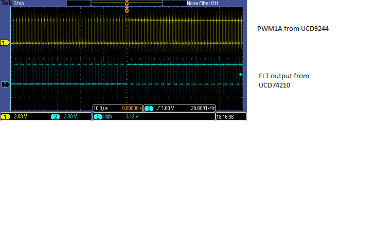
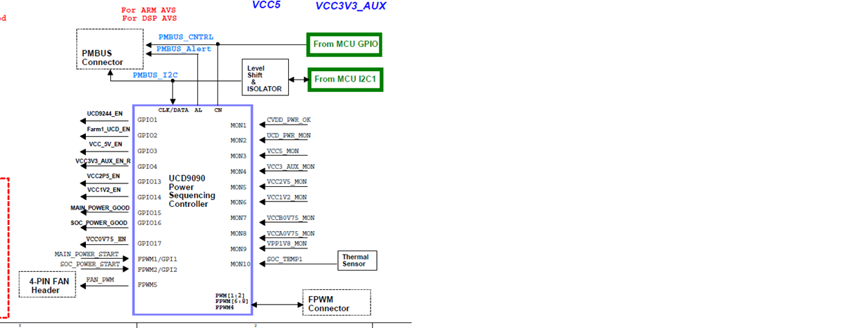
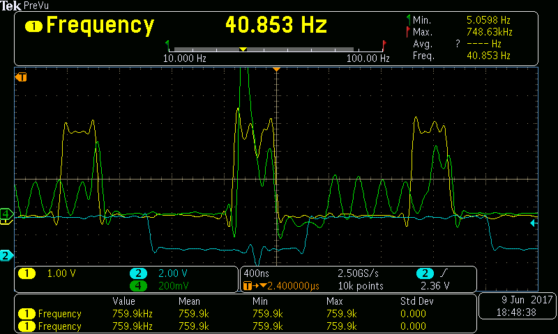
On the UCD9224 we are seeing both of the rails reporting a FLT line from both the UCD74120. PFA the schematics and the oscilloscope plot depicting the FLT line behavior with PWM output.

 Below is the scheme of power design used. We have been re-using the design from K2K EVM from Advantech.

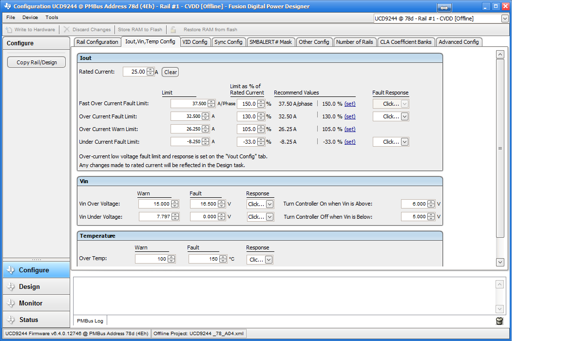
We are observing that the FLT line is oscillating during the PWM cycles. Attached is the oscilloscope capture ,the schematics of the same and the Fusion software captures6574.UCD9244 6.4.0.12746 Address 78.docxK2K-CVDD-PWR-Section-Sch.pdf

  • It looks that UCD74120 has triggered high-side current limit. If this is the case, the PWM should stop after some time. Did the PWM stop? You will also need to compare PWM signal and SW signal to confirm this guess. You will need to zoom into a few switching cycles to see the relation among SW, PWM, and FLT. It is possible that UCD74120's high-side current limit threshold is set too low that triggered OC. 

  • Hi Zhiyauna,

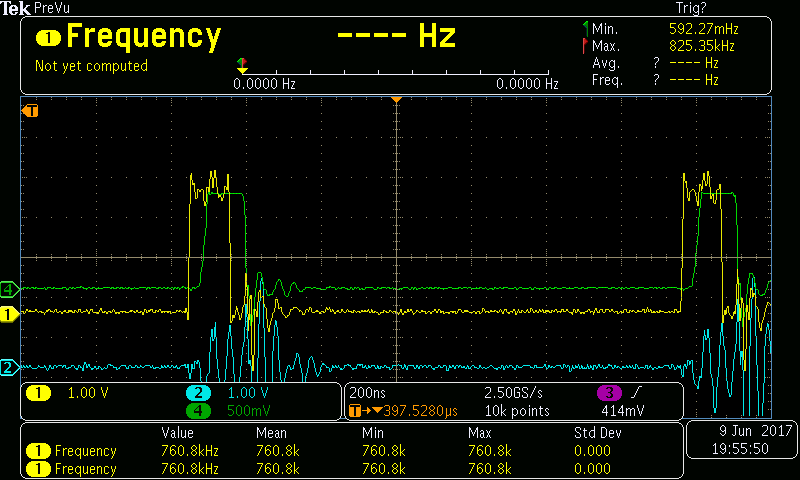
    The earlier captures were provided with K2K SOC disconnected from power regulators. PFA  the captures done with SoC CVDD rail connected to regulators, here we are seeing CVDD not getting generated & PWM being switched off very early, just after SoC power start is issued.

    We have assembled two boards and both the boards exhibit similar behaviour .After SoC power start is issued, PWM looks to be starting and stops immediately because FLT is sensed, In above two captures we are not able to see FLT coming active but the fusion tool report FLT on this channel, This is captured with CRO also as in 2nd image as below.

    CH - 1 (Yellow) - SoC power start

    CH - 2 (Blue) - PWM out from UCD9244

    CH - 3 (Pink) - SW pin UCD74120

    CH - 4 (Green) - FLT from UCD


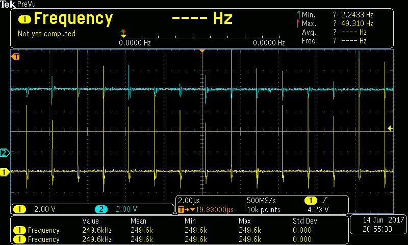
    3. SOC-START_VS_FLT-BRD2_3.png

    CH - 1 (Yellow) - SoC power start

    CH - 2 (Blue) - FLT from UCD

     The FLT pin from UCD74120 coming active is captured here as reported in Fusion tool, the pulse width is around 5nS.


    We need to understand & resolve why the FLT being generated, As of now we shall put 0.1uF cap to gnd on FLT line to filter out any noise/spurious signal.

     We have tried to increase Ilim by changing the Resistor value from 22.6K to 33K on Ilim pin to Gnd (out of voltage divider between BB3 & Gnd to Ilim). On the IMON pin also there is no increase in voltage above 0.5v

    On HS_SNS pin or Boot pin of 74120 there is no drop or dip in voltages when PWM switches on.

     Apart from this if any other pointers, please let us know ,the same can be tried out.


  • Is there a 2-kΩ resistor connected from HS_SNS pin directly to the drain of the high-side FET?
  • Hi Zhiyuan,

    We have connected the HS_SNS pin to VCC 12 volts using a 2K Ohm resistor. Please refer to page 1 of the attached schematics K2K-CVDD-PWR-Section-Sch.pdf
    Best Regards

    LN

  • The 2k resistor needs to be directly routed to UCD74120 VIN pins with the shortest possible distance. Is that correct?

  • Hi Zhiyuan,

    Yes you are assumption is correct. We found that the behaviour is similar whether we connect the load or not. The PWM signal is stopped after few milliseconds from the SOC start. The FLT is continued to be asserted high. The high side current threshold is set 37.5 A.

    I have attached the configuration FYI

  • Hi Zhiyuan
    We would like to understand the theory behind the registers IOUT_CAL_GAIN and IOUT_CAL_OFFSET
    In the UCD configuration picked up from Advantech site the values programmed are 88.125 milliOhms and -4.5 A respectively.

    But according to the following thread
    e2e.ti.com/.../547255
    It has been advised to use the following equations.

    Equation shows below, only if the hardware circuit is set as datasheet recommended:
    IOUT_CAL_GAIN = 47*DCR
    IOUT_CAL_OFFSET = 0.5/IOUT_CAL_GAIN.

    When we played using some values for the above registers we could see simulate IOUT OC fault and IOUT UC fault. But then we could still see that FLT was asserted. So these rules out the following
    • output overcurrent
    • undervoltage lockout (UVLO)
    • thermal shutdown

    So it may be the case of high side current. Could you let us know the possible reasons for the same.

    Best Regards
    LN
  • Hi Zhiyuan,

    We tried few experiments today. We decoupled the FLT line from UCD74210 to UCD9224. The FLT line was pulled down at the UCD9224 side. This ensured that the PWM signal was generated continuously We also observed that there were no faults reported at UCD9244. The experiment was done without the load connected (I mean SOC disconnect and replaced by a resistor load).

    We could see that the VOUT was generated at 1 volt. However we could see that the FLT line was generated at the UCD74120 which was observed using the oscilloscope. The FLT line follows the periodicity of PWM signal. 

    We are not sure as why the FLT lines are generated at UCD74120 and unable to point to the reason for the same.

    Best regards

    LN

  • Since the FLT from UCD74120 is synced with PWM, it is very likely due to high-side over current limit, which is triggered by voltage difference between Vin and SW node. If it is the case, you should see SW note pulse width shorter than PWM. This setting has nothing to do with software. It is programmed by the 2k resistor on HS_SNS pin and a blanking time programmed by resistor on RDLY pin.  

    I think the ringing on SW node mis-triggered the FLT. You can try increasing resistor value on RDLY and see if the problem goes away. Please refer to the datasheet for resistor value calculation.   

  • Hi Zhiyaun,

    We changes the R_DLY resistor to 22K and found that there was no improvement in the PULSE width of SW signal.

    Attached are the screenshots of the same.  I have also attached a similar capture from ADVANTECH K2K EVM

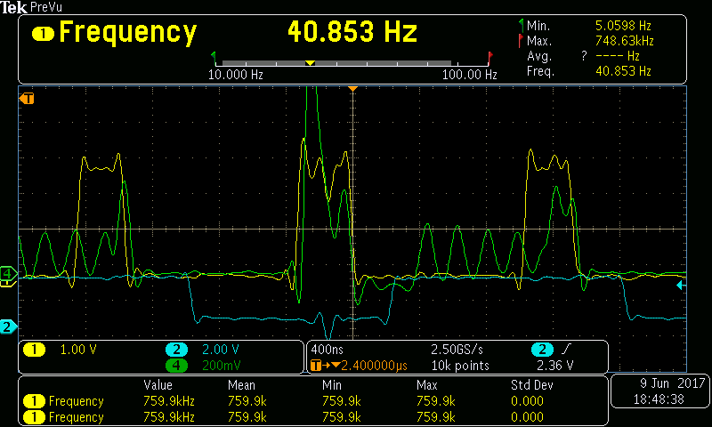
  • Attached is the K2K EVM Capture. We find that the pulse width of SW in this is bigger and cleaner. The behaviour is different in our boards. Please note the following legend

    Yellow = PWM

    Green = SW

    Blue = FLT

  • Hi Zhiyaun,

    Many thanks for your help . As discussed you had requested to check the Waveform at BOOT pin and compare it with the SW pin.  Following steps were followed

    1. The SW should go up to 12 volts during switching - In our case it is rising up to 7V only, our observation is that the high-side mosfet is not turning on fully, which was confirmed by TI, the cause would be no sufficient gate drive.
    2. For above issue, Check Bootstrap voltage at Boot PIN
    3. Capture the Waveform at BOOT

    Following action points were suggested.

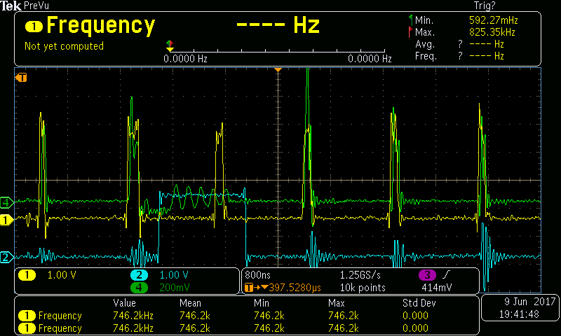
    1. It should be 6 volts above the SW node - In our case it's rising only around 2.6V above SW node voltage(pFA the capture Blue is Boot pin, Yellow is SW node) )
    2. Possibly soldering issue (High resistance) from the VIN to SW node Or BOOT STRAP
    3. Short circuit could be one issue, Check with boot to VGG
    4. Other cause for damage on IC could be high amplitude of ringing, for which adding a snubber circuit with high capacitance should prevent the same.

    Following is the waveform (Blue is BOOT PIN and Yellow is SW signal)

    We found the issue was with the BOOT PIN capacitors. We have replaced and the 74120 is functioning correctly. You may please close this ticket

    Best Regards

    LN