This thread has been locked.
If you have a related question, please click the "Ask a related question" button in the top right corner. The newly created question will be automatically linked to this question.
Hi,
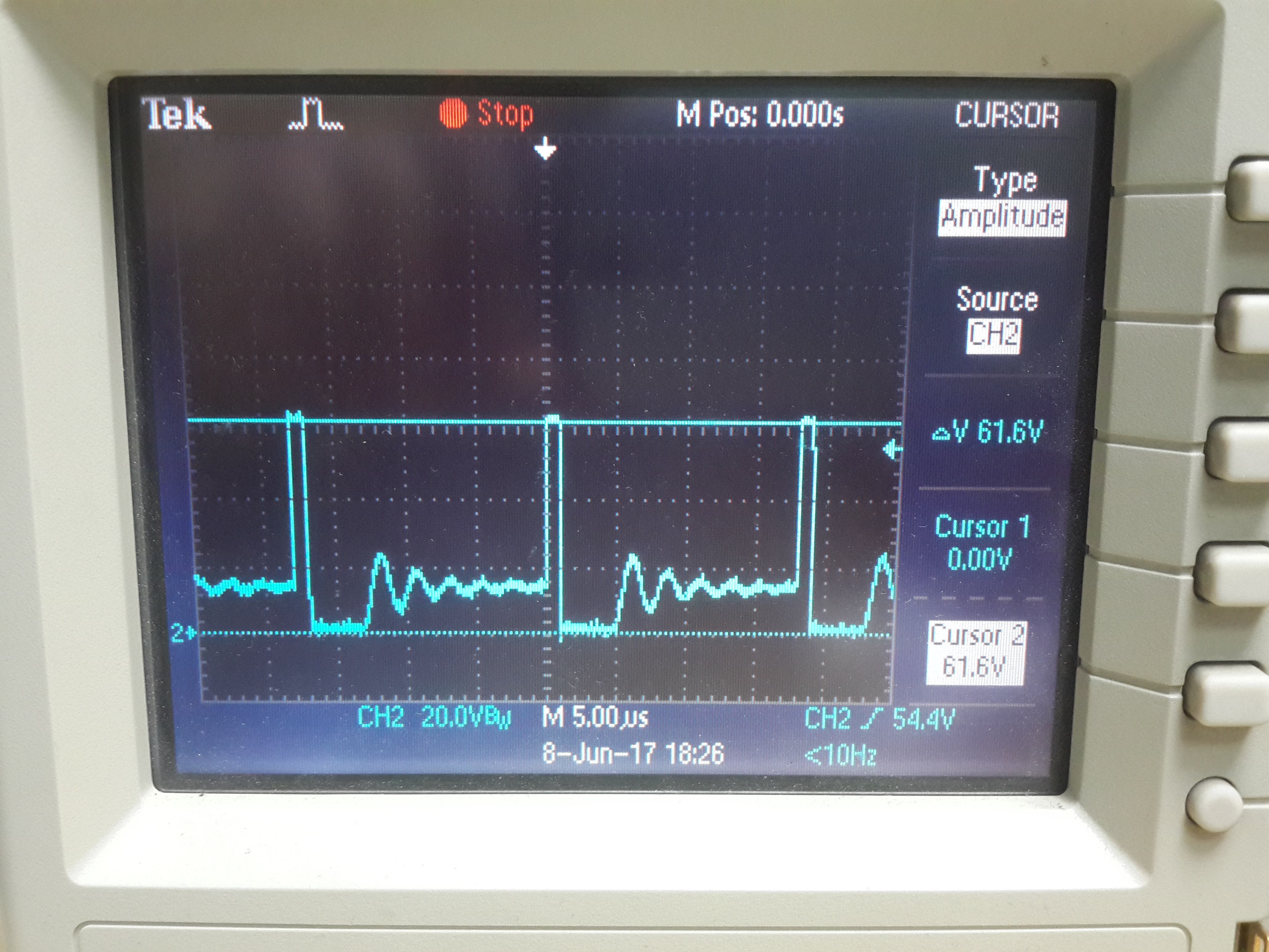
I'v designed a Buck converter using Webench.
The controller is LM5116MHX/NOPB . (webench.ti.com/.../webench5.cgi
The MOSFETs are different from the design, made by TI (CSD19535kcs & CSD19533kcs)
The phenomena is:
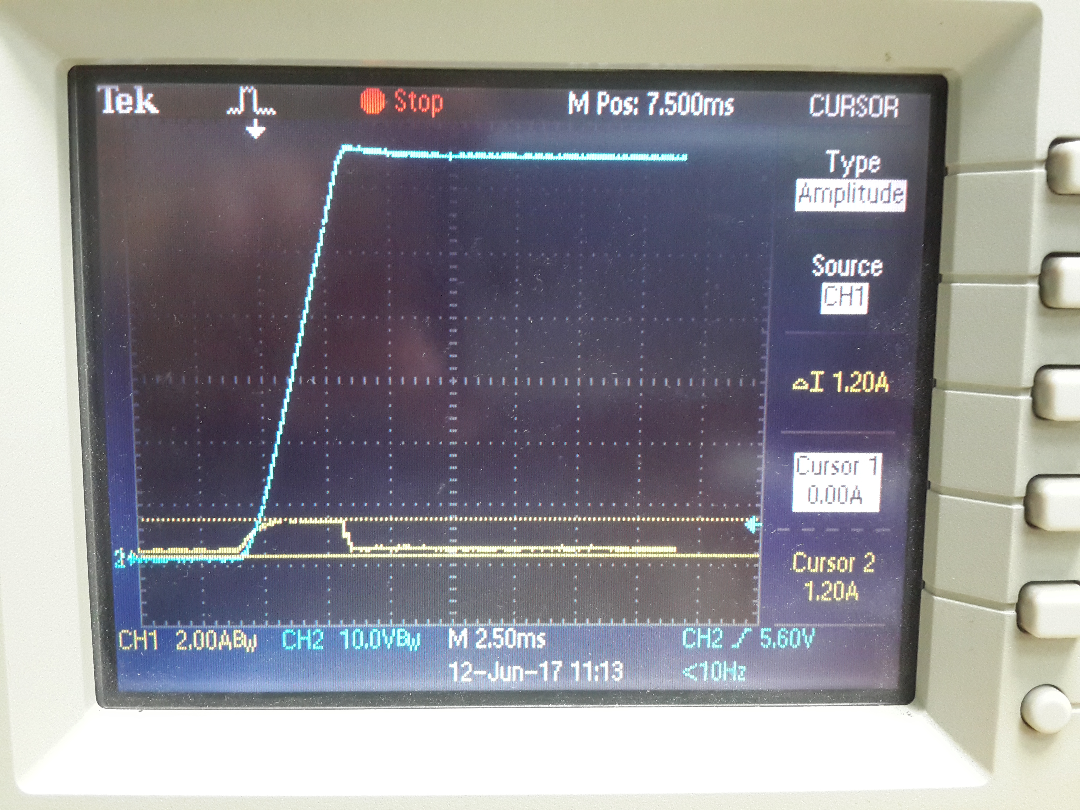
1- No load: if i connect the input to a 31VDC supply, by connecting the + probe (step input), the converter works fine, and i get 12.6VDC output.
2 - No load: if i do the sane with 63VDC (step input), the two MOSFETs and sometimes the LM5116 fail. The MOSFETs are short circuit, and LM5116 fails too.
3 - if i tweak the power supply from 31VDC to 63VDC, slowly, the converter works excellent., up to 10A. The waveforms on DH, LO & SW have square, no ringing at all (from 0.8A to 10A load).
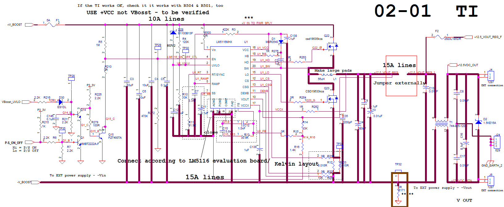
Waveform with no load, 63VDC, SW node. The waveform improves as the load current goes beyond 0.8A . As the current rises towards 1A, the ringing slides to the Right, until it disappears.
Waveform at 0.5A
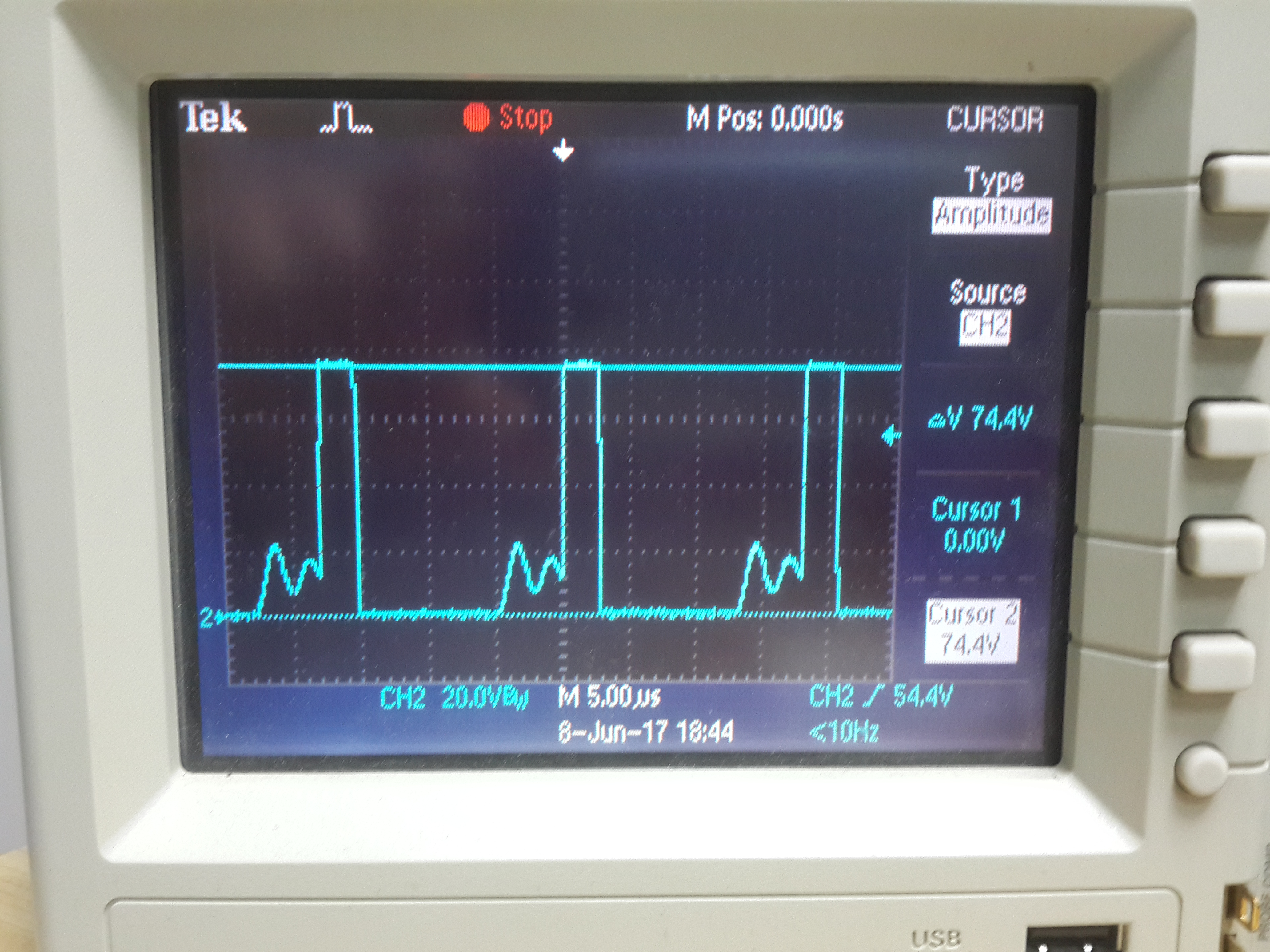
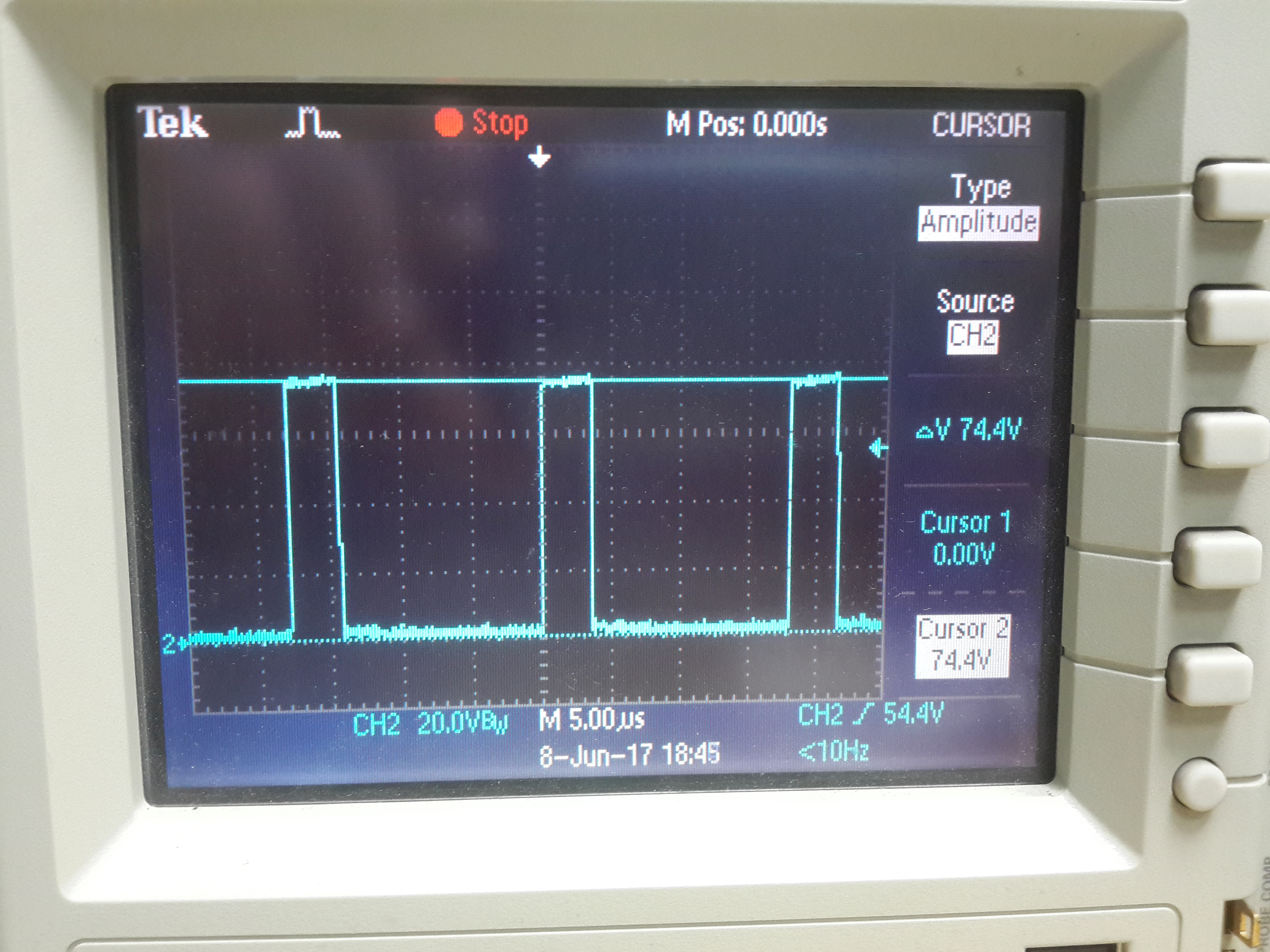
Waveform, at full load, 63VDC, SW node
the design
I cannot read your schematic clearly, but your waveforms indicate you are operating in diode emulation mode. See datasheet section 7.4.1.
As John alluded, there is nothing wrong with the waveform's you posted. The converter is in Diode Emulation mode, so it turns off the low side MOSFET when the Inductor current goes to 0A. The LM5116 can be programmed to be in Forced Continuous conduction mode (FCCM) as detailed in the datasheet. In FCCM, the waveform's will not ring out when in a light load condition.
Are the waveforms above the input voltage and input current?
What is the voltage rating of the FETs you are using, as I cannot read the schematic? Thanks.
Hi David,
Sorry for the late response.
I needed some time to read the 'Manual'....
I used the CE pin for ON-OFF (from my UVLO circuit). The manual indicates to use the UVLO pin for that purpose.
The manual indicates that using the CE pin can mess thing up.
So, now, after the change, i draw 8-10A from the PS, easily, no problem
Thanks again,
Yehiel Nadav
IL
Hi,
Got another question on the LM5116:
The circuit i posted before works fine, in the hot chamber, for hours, 12.6VDCa @ 8A output current, .
It runs off a 68VDC from a PFC pre-regulator, with 5A fuse in between.
when the circuit is 'cold' i can short circuit it (for testing) many times with no problem. It recovers OK.
But, once when the circuit was hot, i did the same, and i blew the fuse and lost (short circuit) the low side MOSFET.
First - Why did it happen?
Second - What is needed to be done, add, to prevent it from happening again, ever.
The circuit must not fail, or have very, very high immunity to short circuit situation.
thanks,
Hello Yehiel,
Did the failure happen immediately upon applying the short or did it happen over time. If it happened over time it is more probably that the MOS device failed due to overheating? You have an option to increase the hiccup time by increase the UVLO capacitor as detailed in the datasheet?
Hi David,
It happens instantly, only when the PS is hot.
The test goes like this: I load the PS in 55C oven, with 8A load. Then, i disconnect the load, and short circuit the output.
Yes, i can increase the hiccup time, but that fault does not exist when the circuit is cold. Why?
Q - Why the the top MOSFET does not fail? only the Fuse & the LOW MOSFET?
Q - What can be done to increase it's reliability?