This thread has been locked.

If you have a related question, please click the "Ask a related question" button in the top right corner. The newly created question will be automatically linked to this question.

UC3846: Duty ratio of PWM to UC3846

Part Number: UC3846

Hi engineers,

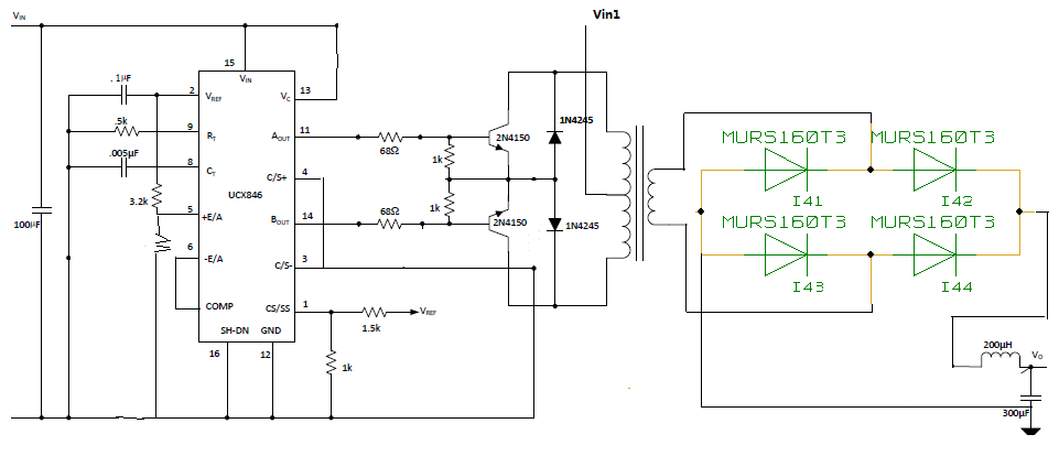
I use UC3846 to implement push-pull application, the present question is that Vin1 powered down, pin11 and pin14 duty ratio is 40%;  Vin powered on, the duty ratio is very small, only about 5%, above the two situations the duty ratio can not be adjustable. Please help to give some support, the schematic as illustrated.

Thank you very much!

Best Regards,

Jenny

  • Hi Jenny,

    Thank you for your interest in UC3846. This device uses current mode control and relies on sensing the primary side current. By connecting CS+ and CS- to ground, you essentially have no ramp to compare the error amplifier output against. I would suggest adding a current sense resistor such as what is shown on page 11 of the datasheet:www.ti.com/.../uc3846.pdf

    Best Regards,
    Ben Lough
  • HI Ben Lough,

    Thanks for your reply. I add the sense resistor, and now the duty ratio can be adjustable. But I still have two doubts about it.

    1. If the dead time is set, but it changed itself, what causes it possibly?
    2.For UC3846, what is the maximum value of duty ratio can be reached?

    Thanks a lot.

    Best Regards,
  • Hi Jenny,

    1. how much of a change in the dead time are you seeing? Are you seeing this after adding the sense resistor? Can you send me waveforms? The deadtime is set by Capacitor Ct. You can calculate the dead time from equation 2 on page 12 of the datasheet:www.ti.com/.../uc3846.pdf

    2. The max duty cycle is 50%

    Best Regards,
    Ben Lough
  • Hi Ben Lough,

    Thanks for your help.

    And I want to ask , does UC3846 adjust the duty ratio by adjusting the setting voltage of the feet 5?
    When the open-loop occasion, the duty ratio can not be adjusted by feet 5. If it is not controlled by feet 5 , by which parameter adjusting?

    And lastly I want to know how to adjust the output of voltage by adjusting the duty ratio?
    Thanks a lot!

    Best Regards,
  • Hi Jenny,

    Duty cycle is determined by comparing the output of the error amplifier (COMP pin) and the ramp signal derived from the current sense pins. If you want to operate open loop, I suggest disconnecting COMP from E/A-. Ground the E/A- pin and apply a voltage to the COMP pin between 0.7 and 4.6V.

    The relationship between output voltage and duty cycle in a push pull is Vout = Vin*D*(Ns/Np)*2.Page 11 of this slide deck might be useful to you:.

    Best Regards,

    Ben Lough

  • Hi Ben Lough,

    Thanks for your patience. But currently I found that UC3846 has a frame-throwing phenomenon at work. I an confusing how to resolve it?

    Thanks very much.

    Best Regards,
  • Hi Jenny,

    I am not quite sure what is meant by frame-throwing phenomenon. Could you provide some details?

    Best Regards,
    Ben Lough