This thread has been locked.

If you have a related question, please click the "Ask a related question" button in the top right corner. The newly created question will be automatically linked to this question.

BQ76930: Cell5 & Cell6 voltage unstable

Part Number: BQ76930

Hi,

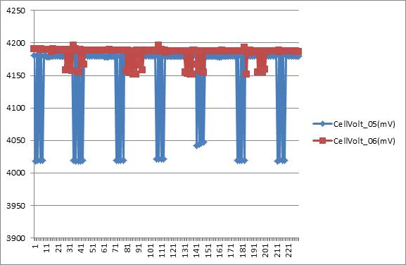
Now measure the voltage at Cell5 and Cell6 we found that the voltage is unstable as the table below:

The schematic is the same with the previous one except of the diodes that cause damaged

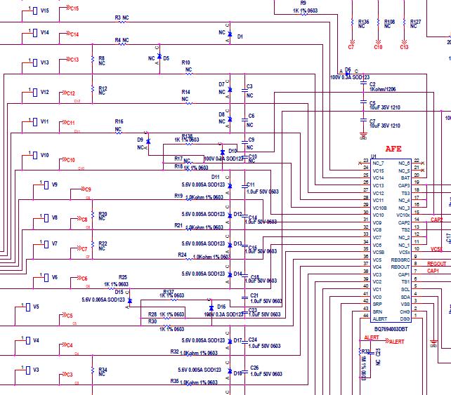
We have tried to remove D15 or connect D15 from CV6 to VC5x, it's more unstable, FYI

Could you please help on this? Thank you.

  • Hi Chentsu,
    What is the operating condition when the waveform was captured, is cell balancing operating?
    There are several things which can typically disrupt the cell 5 and cell6 voltages:
    - Missing Rf or Rc capacitors, but you have those.
    - High impedance source such as a resistor cell simulator and balancing.
    - Common path resistance in the cell 5 connection (V5 or C5) to the low impedance cell or source. See the http://www.ti.com/lit/slua749a figure 8. This tends to pull 1 cell up while the other goes down.
    - Large filter capacitors (1 uF Cc with the 1k Rc) can disrupt the lower cells in a group due to long settling time. This may affect cell 6 but should not affect cell 5.
    - Using a schottky for D16 and having hot thermistors. Approximately 300 uA will bias the thermistors on the separate 2 second intervals causing VC5X to move approximately 300 mV. If D16 conducts cell 5 can measure low. The duty cycle seems long in your capture for a thermistor effect.

    I misunderstood the zener diode placement on the first schematic mistakenly thinking they were across the cells rather than the IC inputs. When balancing a single cell the voltage across the next cell goes to about 1.5x the cell voltage. If you notice www.ti.com/.../slua775 figure 5, imagine if VC2 does not move. 1.5x 4.2V would be 6.3V. Since you have the 5.6V zeners they will be conducting and pull on VC2 in this example. If we are balancing every other cell the voltage on the unbalanced cell would try to double and the zener would have more bias. Both cell 5 and cell 6 appear to decrease in voltage with cell 5 being the largest. I don't see a reason for that. If it were settling time enhanced by the zener current cell 6 should have the larger disruption since it is measured first.

    I hope this is helpful. You will likely have to measure with a scope to see what is moving. The area of interest would be the short "measurement" portion of the waveform such as www.ti.com/.../slua775 figure 5, but looking at the signals relevant to cells 5 and 6.