Other Parts Discussed in Thread: TINA-TI
Hello dear hosts!
I have two separate questions about ucc28950 application:
1)could current sensing transformer be moved from the supply rail to the transformer's primary? will controller operate correctly with ct in the power transformer primary?
2)should dc blocking capacitor be placed in series with transformer's primary to prevent core saturation in the situation when pwm duty cycle changes. so when previous duty cycle is different from the current,transformer does not get a dc bias that can saturate the core?
Thank you!


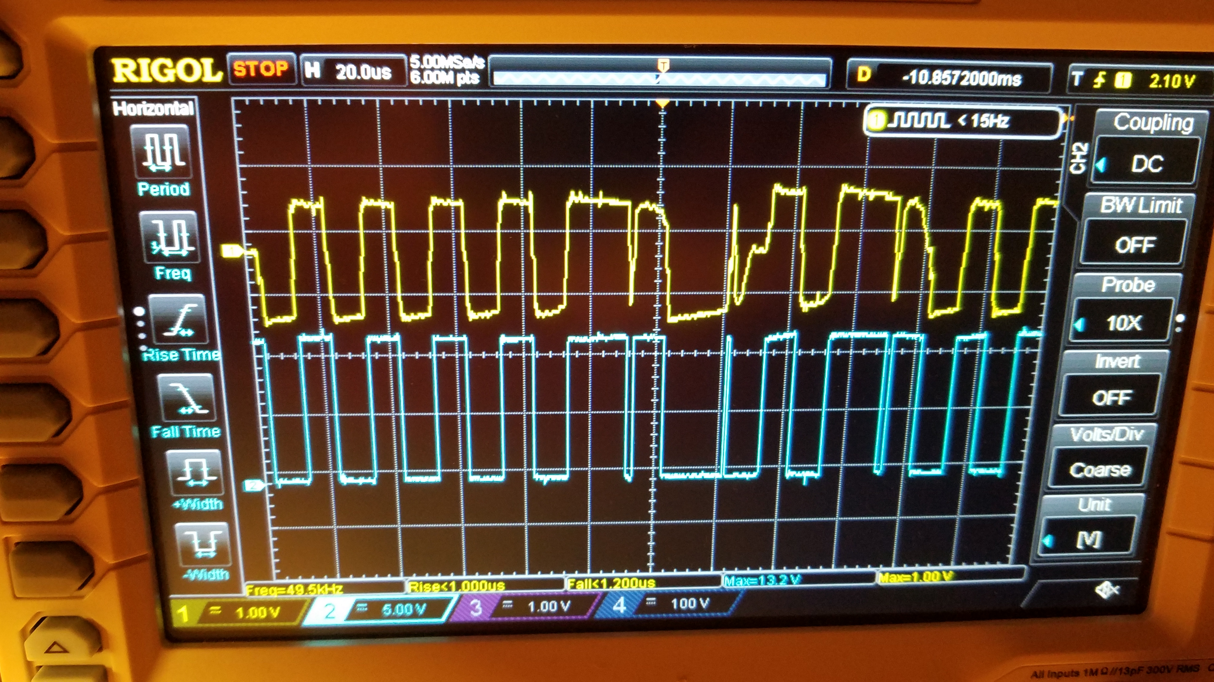
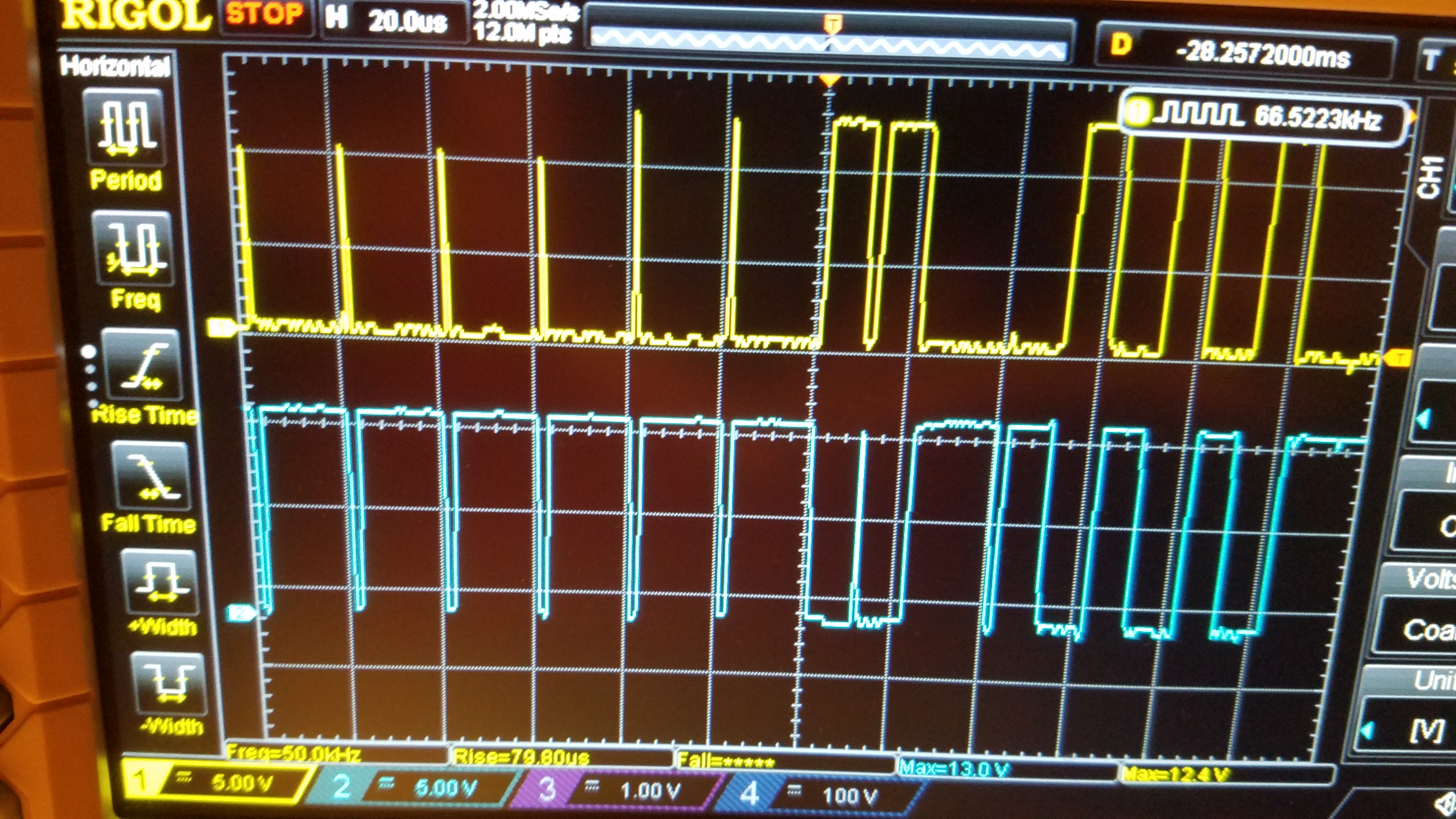
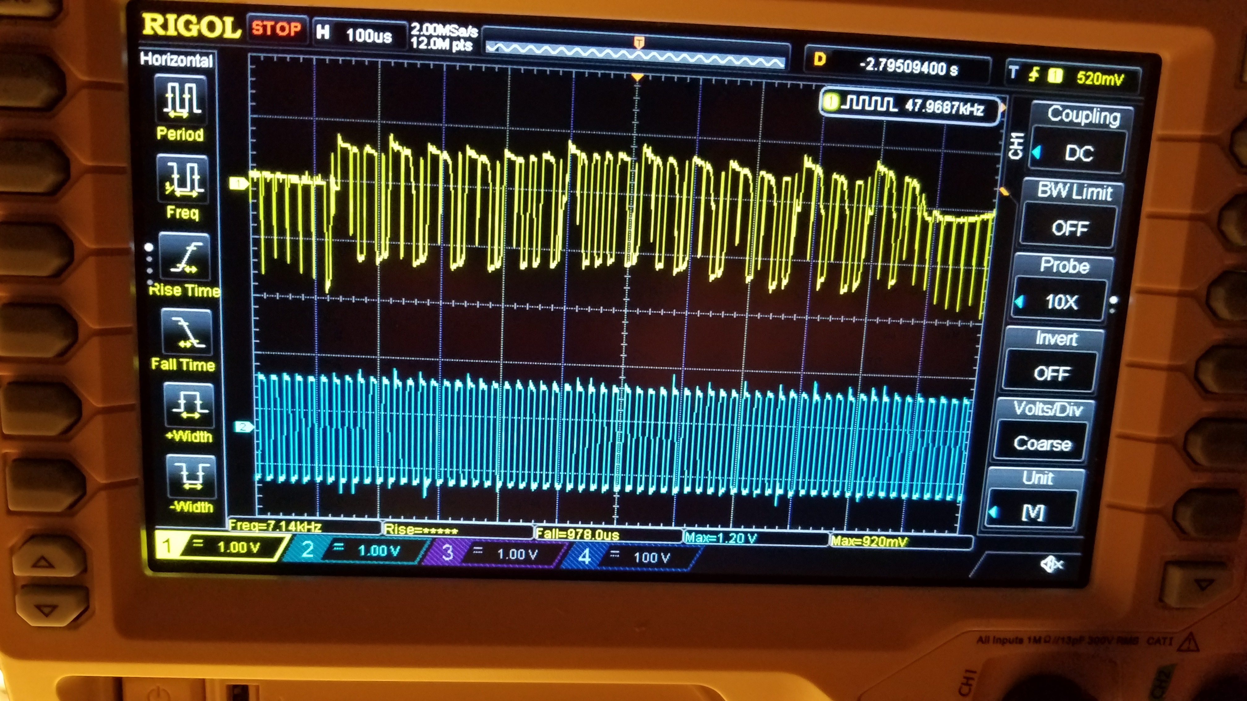 Here's the most awefull situation,at startup. yellow its CD leg and blue is AB leg gate transformer signals.