This thread has been locked.

If you have a related question, please click the "Ask a related question" button in the top right corner. The newly created question will be automatically linked to this question.

TPS61089: Vout =12v ,Iout=4.5A

Part Number: TPS61089
Other Parts Discussed in Thread: TPS40210, TPS43061, PMP9772, TPS61088, TLV61220

Hello,

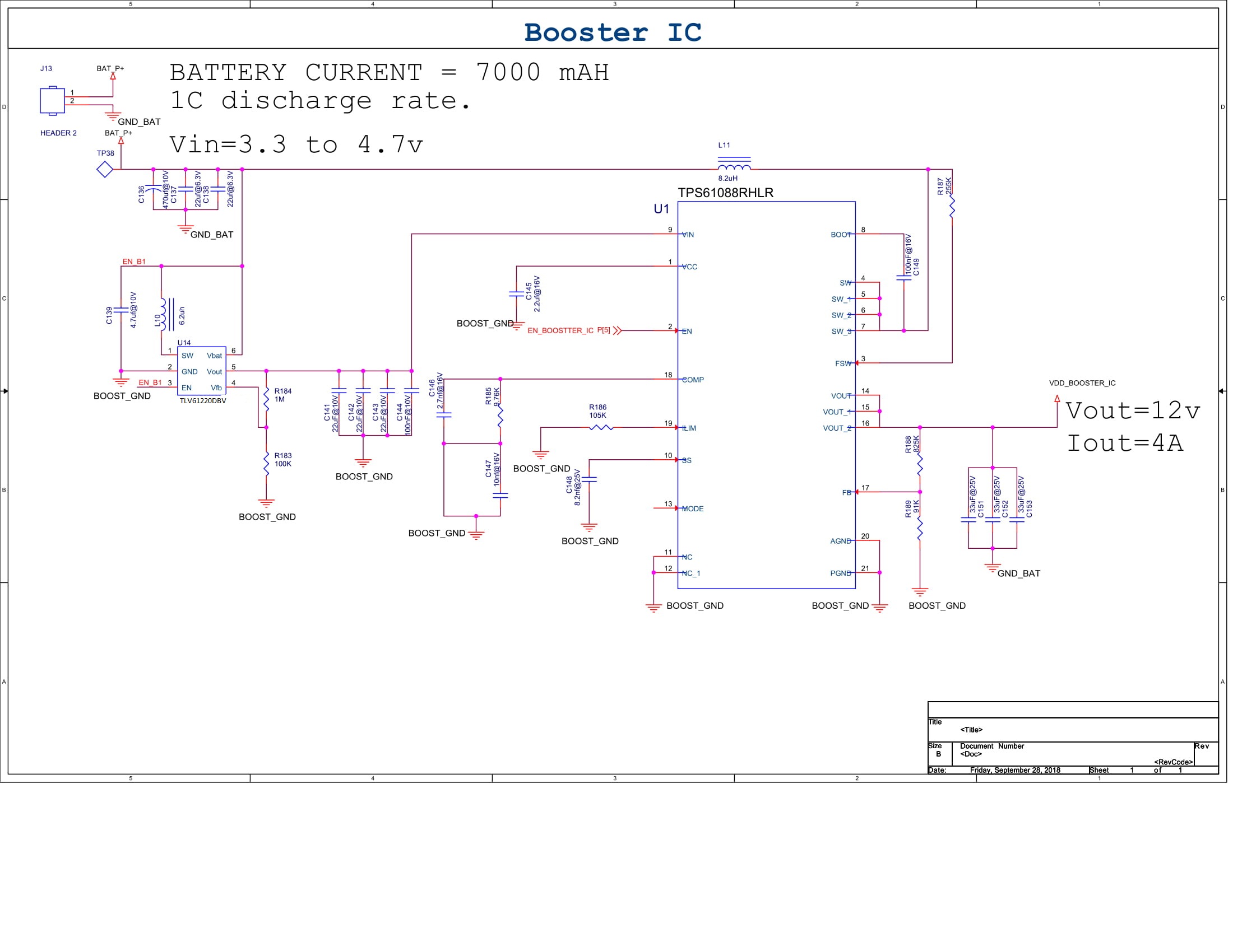
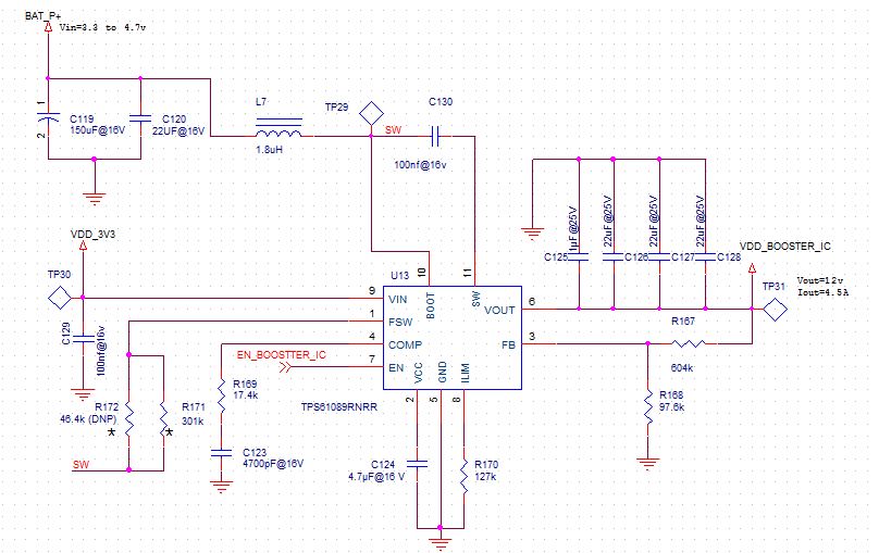
I am designing a boost circuit using the IC TPS61089 Parameters of the circuit are mentioned below :

1)Input parameters = batttery powered rated 4.7v 7000mAH 1C discharge rate.Min Vin(min)=3.3V.

2)Output Parameters = Vout=12v and Iout=4.5A.

Below is the schematic that i have designed is this design correct as per my output parameters or any changes are there.

I tried to simulate the circuit in the web-bench tool but not getting results.

So Kindly provide solution as per the output parameters...!!! 

  • Hi Sir,

    12V/4.5A is too high for the TPS61089. Currently, non of the integrated boost converter could support such high power. Suggest you use boost controller TPS40210 or TPS43061.

  • But my input min voltage are 3.3 and max 4.7 v...this ic need min 5 v to operate.Also suggest any other methods to achieve this parameters.

    Also if i change my input voltage to 12 volts then accordingly to that please kindly suggest me some IC.

  • Hi Sir,

    Do you have a 5V supply in your circuit. you can connect the battery to the inductor and connect the 5V to the IC's Vin pin.

  •  Hello,sir

    As per your explanation i am attaching  some drawings is this what are you trying to say...!!!

    If yes then please provide the explanation in the detail.

    Actually my application is totally battery operated and also i have size constraints.And my source in the circuit is Battery only...!!

    Is there any other IC or method which would bridge my approach of the booster IC.

    Waiting for your response..!!

  • Hi Sir,

    Very good question. If there's only battery in your system, then you need to add a tiny boost convert to boost the battery voltage to 5.5V, then use this 5.5V to supply the VDD pin. Like  the TI design PMP9772 do.

  • Hello,

    Thank you for the solution...can you please provide the footprint datasheet of TPS61088RHLR , beacause the datasheet of TPS61088RHLR does not have its footprint data.

    Waiting for your reply...!!!

  • Hi Sir,

    You can found the detailed   footprint data on page 29.

  • Hello,sir 

    I am attaching you the schematic that i have made...please check and suggest if there is changes in schematic....!!!

    The circuit input parameters are :

    Battery powered 4.7v and 7000 mah with 1C discharge rate.....!!!

    The circuit output parameters are :

    Vout=12V

    P=40 to 45w

    I=4A

    Is it necessary to provide 3.7 V 12000 mAH to get output power of 40 to 45 W power.

    Or i can achieve 40 to 45 W power from  3.7 v 7000 mAH  configuration...!!

    Also provide details about minimum in put values of the booster Ic in order to get 12 V 35 W and 4A of current....!!!

    Waiting for the reply.....!!!

    Also i refereed to datasheet about footprint but still didn't got..!!!

    Can you please provide data...!!

  • Dear Sir,

    The tiny boost converter is used to supply the Vin pin TPS43061, not TPS61088. In your application, the battery voltage is high enough to supply the TPS61088. The problem is the output power is too big for TPS61088(or Vin should be higher than 4.5V). So you need to use TPS43061 plus a tiny boost converter.

    I'll draw a schematic for you within these days, please wait in patience.

  • Hello,

    Thank you for your valuable output.waiting for the schematic..!!!!!

    As per the evm of the PMP9772 ,the output voltage of TLV61220 IC is set to 5.5v as per the electrical parameters specified in the datasheet.So my input voltage of the TPS61088 will be 5.5V(Greater than 3.7v).

    Also please let me know if i am taking wrong approach or missing any thing in the calculation.....!!!

    I have generated the result of TPS61088 for the 12 V output and 4 A current from the web-bench.

    Please find the attached result files...!WBDesign25.pdf

  • Dear Sir,

    The schematic is OK if the Vin is >=5V.

    For TPS61088, the internal logic circuit is supplied by the higher voltage of Vin and Vout. So for your application, at startup, the internal circuit is supplied by the Vin, after startup, it is supplied by the 12Vout.

    But for PMP9772, both Vin and Vout is low. So need to boost its Vin pin voltage to 5.5V to make sure the internal logic is supplied by a high enough voltage to get high efficiency.

    So it seems you get confused about the application. Please read PMP9772 carefully, then you can know why it need a tiny boost. For startup(Vin need to higher than 2.7V) and also for high efficiency after startup (it be better that Vo should be >=5V, if Vo is lower than 5V, then Vin pin voltage should be >=5V to ensure the drive circuit work normally. ).