This thread has been locked.
If you have a related question, please click the "Ask a related question" button in the top right corner. The newly created question will be automatically linked to this question.
Hello,
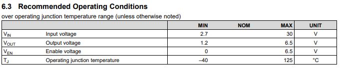
We are using TPS70950DBVR in our PCB and our max input voltage is 24v. However, we are having random issues with the board burning out due to this component. On our schematic it is U1. Any incite on what the cause could be?083-1000-Rev3.0 No Freeze Control Board Assy Drawing.pdf083-1001-Rev3.0 No Freeze Control Board Schematic.pdf083-1000-Rev3.0 No Freeze Control Board BOM.pdf
Hi Brad,
The maximum recommended operating voltage for the TPS709 enable pin is 6.5 V.
Since the TPS709 in your application has an input voltage of 12 V typical and 24 V max, you should not be tying EN to IN. Based on the schematics you have provided, it looks like there are no other rails that can be used for an enable signal. You may have to add one or use a voltage divider at the regulator input to ensure that the enable pin voltage is always 6.5 V or lower.
Thanks,
Gerard
Hi Brad,
The TPS7B69 would be suitable to my knowledge of your application. It supports up to 40 V input, up to 150 mA load, has a fixed 5 V output version, and comes in the SOT23-5 package. It does not have an enable pin so there is no need for more components. If you have any additional performance requirements you can do a parametric search of TI's LDO portfolio on the TI website here:
Thanks,
Gerard