This thread has been locked.
If you have a related question, please click the "Ask a related question" button in the top right corner. The newly created question will be automatically linked to this question.
Hi,
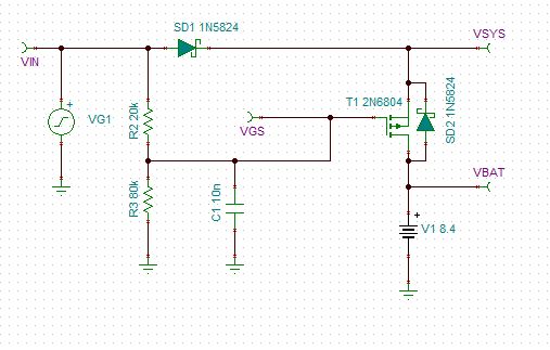
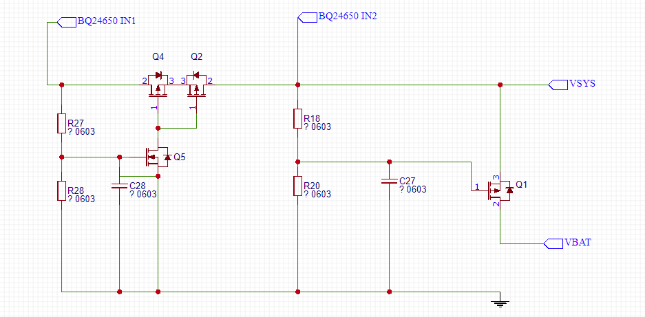
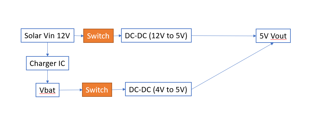
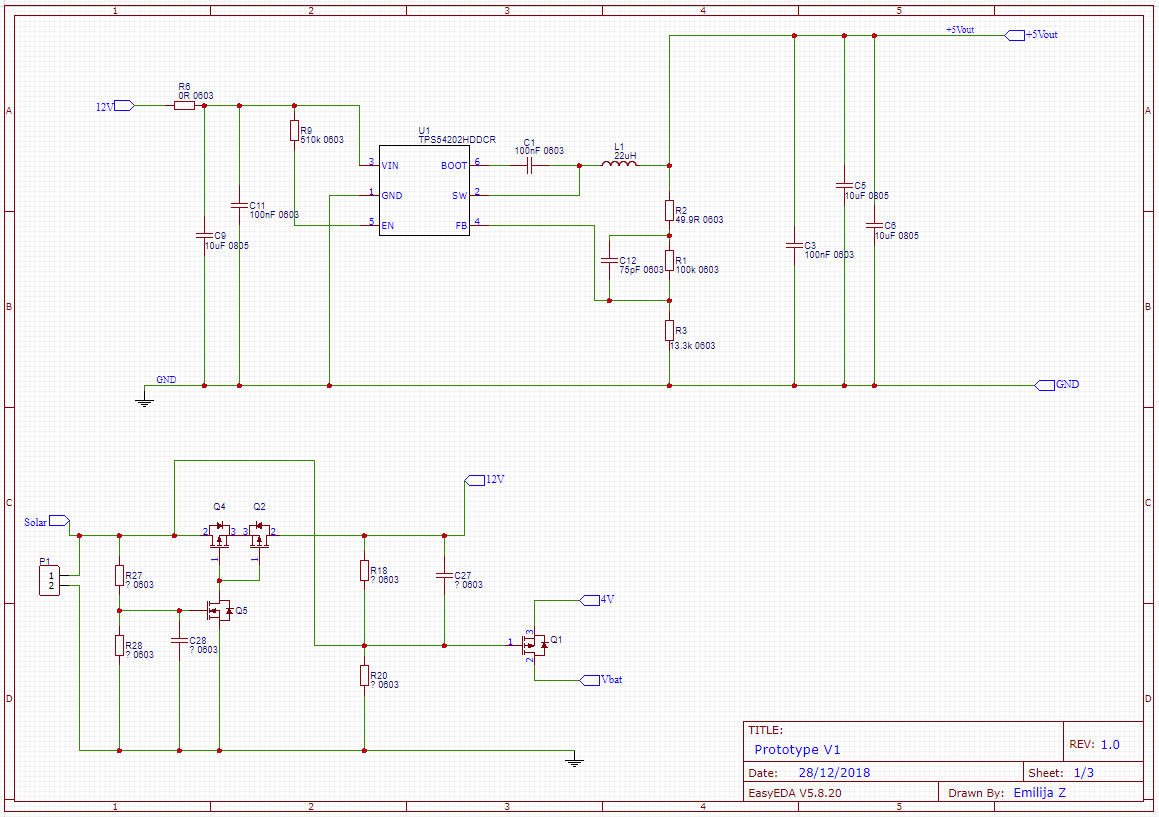
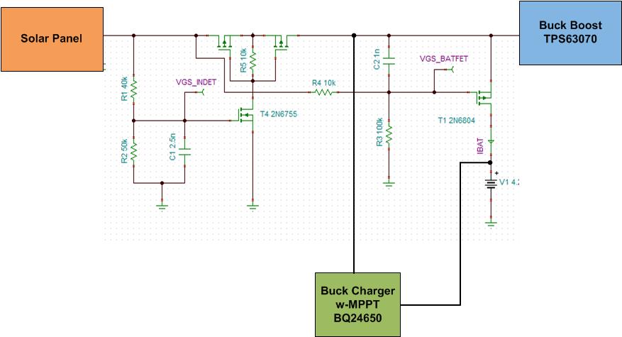
BQ24650 doesn't provide a power path but I would like to try and design a power path circuit using PFETs to be able to supply the power to the system even when the battery is not connected or low. Can you please suggest the design? Is it possible to prioritise the system load over a charger circuit? If there isn't enough current to supply the load and charge the battery I would like to use all available current to supply the load rather than charge the battery.
Thanks!
Emilija
Hi Emilija,
The dynamic power management (DPM) of a charger priorities the system load over battery charging. It requires changing internal control loops. Implementation with external circuit would be extremely difficult. Adding a PFET for power path is possible but the timing control of the FET to prevent shoot through during the power path switching could be complex. TI has host controlled chargers with power path and DPM that can be used for solar charging. This is a blog talking about the application e2e.ti.com/.../optimizing-solar-power-with-battery-chargers.
Hey Emilija,
For the power-path, you could implement something like the following. You would need to tweak the threshold voltages and capacitor value to add some turn on delay as well as select the appropriate P-Ch FET. Remember here that the voltage will either be the battery voltage or a diode drop below the input voltage.
As far you question about the BQ25895, I am a little confused as it seems you are putting a regulated DC/DC in front of the charger? Will the front-end DC/DC provide power point tracking for you? As far as the charger, the default VINDPM voltage will be 5V - 600mV = 4.2V if the unloaded output voltage of the DC/DC is indeed 5V. This means the charger will allow it's input voltage to crash to 4.2V and then subsequently regulate at that threshold.
Regards,
Joel H
Hi Joel,
Please see my schematic idea below. I would like to replace diodes by PFETs to reduce the power loss.
Do you think that could work?
Why do I need to add a delay to switch to a battery power supply?
As far you question about the BQ25895, I am a little confused as it seems you are putting a regulated DC/DC in front of the charger?
-- I need to use a dc-dc because my input voltage can be up to 14.5V and the maximum input votlage of BQ25895 is 14V.
Will the front-end DC/DC provide power point tracking for you? As far as the charger, the default VINDPM voltage will be 5V - 600mV = 4.2V if the unloaded output voltage of the DC/DC is indeed 5V. This means the charger will allow it's input voltage to crash to 4.2V and then subsequently regulate at that threshold.
--- Can I increase the VINDPM voltage to 4.8V for example? Would I need a host controller?
My prefer option is to use BQ24650 with a power path design. I just need help to design it.
Thank you very much!
Regards,
Emilija
Hi Joel,
Sorry for the delay, I was off work.
I used Q2 instead of the diode from BQ24650 D1 for a reverse protection.
I added another PFET Q4 and NFET to turn Q4 and Q2 on. Is that what you meant? Can you please explain a bit more?
How long I need a delay for? I dont want the system to loose power and turn off if the the power path switches between the solar panel input and the battery. I'm worried that the solar panel input will be unstable and will keep switching between the battery and the solar input.
"As far as the back-to-back FETs you drew up, I would just use a single PFET with its body diode in the direction of VSYS from VBAT (effectively Q1 only in your circuit). This will achieve power-path. "
Did you mean the to use a single FET with its internal diode? Will it give a reverse polarity protection?
Is it okay to connect IN1 and IN2 to the points of the BQ24650 circuit as I drew it earlier?
Please review my schematic. I'm not sure if it will work.
Thank you!!
Hey Emilija,
You are close to what I was suggesting. For reference, this is a modification to the circuit you attached:
The 1uF at the input and 40uF + 1A load at the output is an example of what is part of the required charging circuitry. The rest is similar to what you gave but adjusting the drive of the BATFET (Q1 in your circuit).
As far as the solar panel and battery interaction: We only want the delay long enough to allow the BATFET to be turned off before the input protection FETs turn fully on. You will have to play around with the capacitance and resistor value in a SPICE simulator to get a feel for how much voltage drop you will see based on a particular delay you implement. The voltage droop and any oscillation will depend on several factors including:
1) System load current and output capacitance
2) Charging current
3) Delay based on RC and voltages applied to the control NFET and the P-Ch. BATFET.
4) FET threshold voltage
5) The charger's programmable MPPT pin voltage setpoint
6) Resistor divider ratios and lowest operating voltage of the panel
This is not a complete list but it will get you started. Again, the main reason for the delay is so your input does not source as much current as possible into the battery.
Regards,
Joel H
Hi Joel,
Thank you! I will try simulating and building a PCB. Is it correct to replace D1 from the typical applciation of BQ24650 by T3 and T2?
Basically connect T3 left to D1 anode and T2 right side to D1 cathode?
I'm still not sure how two PFETS common source allows the power to pass through? How can power go from the source to drain of T2?
Regards,
Emilija
Hey Emilijia,
I just tested this on both TINA-TI and LTSpice and the result was the same as what I stated before. Make sure your spice model is utilizing a real PMOS instead of an ideal model without a body diode. Also check your simulation conditions. The voltage thresholds have to be set such that Q5 will turn on sufficiently and Q1 will turn off sooner than Q4 and Q2 turn on.
The back-to-back input PFETs are needed so you do not short the solar panel and the battery. Right now, Q7 in your circuit has no function because it is always pulled to ground. Effectively, the battery can push current to the input with this always on PFET.
I would also remove R18 or at least put it in series with the "Solar" and the Q1 gate.
As far as your comments about using the BQ24650 for the MPPT and the extra DC/DC converter. Since you are looking for a fixed 5V rail, I would recommend using the BQ24650 plus a buck-boost DC/DC converter such as the TPS63070. In this case, you are looking at a model like this:
Regards,
Joel H
Hi Joel,
I thought I replied but I cant see my message from today.
The design you suggested looks great! I will design a PCB and build it.
I've just got a few questions. Where do connected points IN1 and IN2? I dont really need Q7 if I have two back to back FETs before. Do I just short IN1 and IN2? Or do I connect left side of the first FET to IN1 and right side of the second FET to IN2?
Also I'm not sure what voltage should I set as MPPSET? I read that I should set to 80% of the VIN. But I have two solar panels I might be using either 6V or 12V. Do I set 80% of 6V?
Thank you for your support!
Regards,
Emilija
Hi Joel,
Should I add a diode to prevent the leakage current going back to the charger as suggested in this document? http://www.tij.co.jp/jp/lit/an/slva829/slva829.pdf
The document states that just having a diode and no extra capacitor will remove a battery detection function. Maybe that would be a good solution for my application? I could connect the load to the battery and I wouldn’t need a power path circuit? Would it work? Or will it have issues as the battery will be always in charging mode because the load will draw current and that means that life of the battery will be reduced?
Also I found this power path design document:
http://www.ti.com/lit/ug/sluu410/sluu410.pdf
It looks more complicated than my design and it’s using a PG pin or STAT2. Do you think I need to take anything from this circuit?
I would like to keep it simple, but I just wanted to check with you if anything’s missing.
Please see my schematic below. Let me know if there is anything wrong.
Thanks.
Regards,
Emilija
Hi Joel,
Thank you for your comments.
I'm not sure about MPPT voltage setting. We require to use either 6V or 12V solar panel. If I set MPPT voltage to 5V will it still work with 12V solar panel? What will happen if a 12V panel voltage drops to like 10V. Will the charger adjust the charging current?
Regards,
Emilija