This thread has been locked.

If you have a related question, please click the "Ask a related question" button in the top right corner. The newly created question will be automatically linked to this question.

BQ24610: how about Bq24610 Resistance is Out of Range

Part Number: BQ24610

Dear ti,

        I have read the slua585 design resources,there is a  description of a paragraph  in the below:

BAT Output Capacitor or Resistance is Out of Range
For host control charger, a data sheet will give a recommended inductor and capacitor value base on the
LC resonant range.
For stand-alone charger, it not only has a LC resonant range, but also has Cmax_wake or Cmax_dis
calculation which is derived from the battery detection parameter [see bq24610 data sheet (SLUS892)]. If
the output capacitor is over Cmax, the status pin will flash even when battery is absent.
Also, if the resistance is too high between charger output and battery terminal, the charger will run in and
out of charger termination.
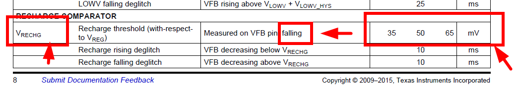
Rbat_max = Vrch/Iterm
Vrch: Recharge threshold voltage; mV/Cell
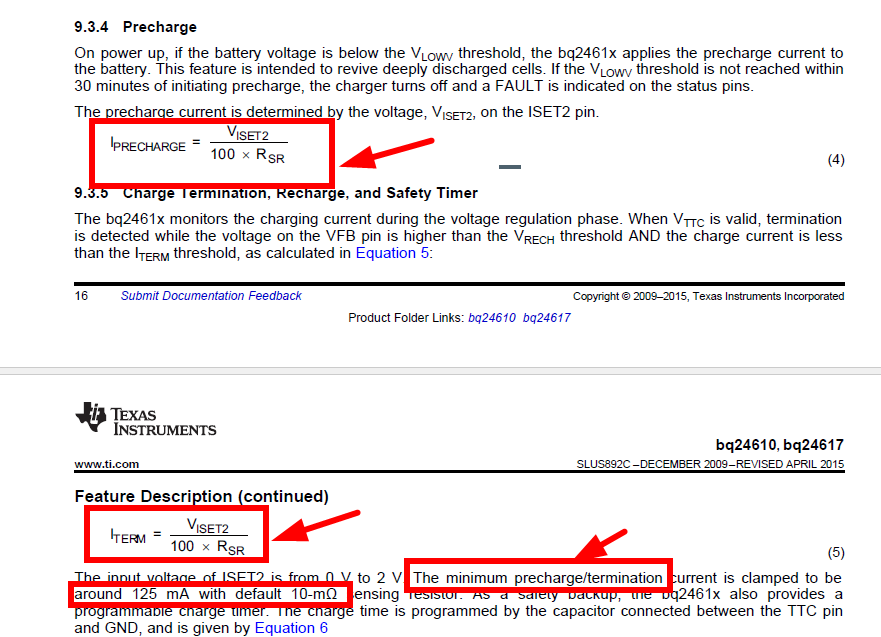
Iterm: Termination current.

Rbat_max is the resistance between charger output and battery termina?

Rbat_max is the internal resistance of cell?

Rbat_max is  The sum of the two ?

Looking forward to your reply.

Thank you.!


  • Hi Sea,

    The Rbat_max in the application report SLUA585 is related to the recharging threshold Vrch. When the current Iterm flows due to the battery voltage drops to the Vreg - Vrch, the voltage at the BAT terminal increase due to (Rbat-max) x Iterm reaches Vrch, so the charging is terminated right after the charging starts. The Rbat_max is the resistance causing the voltage increase, so it is the sum of battery internal resistance and the resistance between charger BAT pin and the battery terminal.
  • hi, ezhao!

        hank you very much for your reply. 

       in the bq24610 data sheet  The following information :

    1.

    .

    2.

    3.

    4.

    From the information above, Irecharge=Iterm .Tprechg(min)=1440s, Vrch for 35mv to 65mv.

    In my design,The cell is 18650,4.2V/3500mah, The battery is 4s2p, 16.8V/7000mah, Battery internal resistance <300mΩ,

    so: Rbat_max=Vrch/Iterm  ,and Iterm=Vrch/Rbat_max=Vrch(min)/Rbat_max=35/300=117mA ,The Value of Iterm<125mA(The minimum precharge/termination current),

        in the case,how to make surethat  the Bq24610 normal operation in prechge safe time and how to make sure that  the Tprechg<1440s

    1.Raising the Iterm/ Irecharge threshold?

    Look forward to your reply !

     thanks!

  • PS: in my mind, Rbat_max is the resistance between charger output and battery termina. the internal resistance can be increased by time.

  • Hey sea,

    I think you misread that. There are two parameters here. Eric described "Recharge" while you are referring to "Pre-charge".

    These are not the same thing. As Eric mentioned, you just want to minimize the resistance between your battery and the SRN pin of the charger. Using the spec that VRECHG is between 35mV and 65mV, we want to minimize the resistance such that it is less than 35mV to 65mV divided by the termination current, ITERM. In other words, VRECHG / ITERM = Rbat_max.

    As you mentioned, you don't have much control over the internal battery resistance, but you do over the line resistance between the battery and the charger.


    Regards,
    Joel H
  • HI! 

        Joel H,thank you very much for your reply. 

         in the bq24610 datasheet  ,

          ITERM=Iprecharge=Viset2/(100*Rsr);

        in the  slua585

       VRECHG / ITERM = Rbat_max  =>ITERM=VRECHG/Rbat_max

      and, As ezhao  mentioned  Rbat_max  is the sum of battery internal resistance and the resistance between charger BAT pin and the battery terminal.

      adn,the Battery internal resistance provided by battery manufacturer, if the Battery internal resistance Too high, Cause the  ITERM to become smaller ,also Cause Iprecharge become smaller;

      for example

     In my design,The cell is 18650,4.2V/3500mah, The battery is 4s2p, 16.8V/7000mah, Battery internal resistance <300mΩ,

    so: Rbat_max=Vrch/Iterm  =>Iterm(min)=Vrch/Rbat_max=Vrch(min)/Rbat_max=35/300=117mA ;

          ITERM=Iprecharge=117mA

            but The Value <125mA(The minimum precharge/termination current);

              in the case,How to handle it correctly?


  • Hi Sea,

    You are considering the worst case for the charging specification and battery impedance. The 35mV is very low ppm event. You might want to do some experimental test to check the typical margin you have. If you have to consider the worst case combinations, then the sensing resistor RSR has to be increased.
  • HI! 

     in the  bq24610 datasheet

      The minimum precharge/termination current is clamped to be around 125 mA with default 10-mΩ sensing resistor.

     the sensing resistor RSR has to be increased. this can solve the  The minimum precharge/termination current too small.

    but ,In my design,The cell is 18650,4.2V/3500mah, The battery is 4s2p, 16.8V/7000mah, Battery internal resistance <300mΩ,

           Rbat_max=Vrch/Iterm  =>Iterm(min)=Vrch/Rbat_max=Vrch(min)/Rbat_max=35/300=117mA ;

           ITERM=Iprecharge=117mA

    if I set the Iprecharge=117mA,This will lead to another problem.the  Iprecharge is too small,how to make sure that  the Tprechg<1440s?

    Tprechg: Precharge safety timer range .the  range form 1440s to 2160s。

    Or another understanding:

         ITERM=Vrch/Rbat_max,the ITERM is the min value.

         in  design,we only make sure the value of the seting ITRTM greater than ITERM?

     for example: 

    in my design ITERM(min)=Vrch/Rbat_max=117ma,

    if we set the Iprecharge= ITERM=350ma>117ma,(Iprecharg=350ma can make sure  the Tprechg<1440s)

     this is ok?

    All the above questions,I just want to know how to set the value of the Iprecharge.

    Can you recommend a value of the Iprecharge  in my design?

    Look forward to your reply !

     thanks!

  • Hey Sea,

    As far as the pre-charge setting, you will need to determine the minimum voltage you will let your 4S battery pack drop down to. From there, determine the voltage to exit Pre-charge by using the VLOWV voltage spec and the resistor divider ratio to the VFB pin.

    As an example in your case, the minimum voltage may be 2.5V/cell (so 10V for the 4S pack). If you are charging to 16.8V, the resistor divider network to VFB will look something like a 700kOhm and 100kOhm. Knowing this and VLOWV rising threshold = 1.55V, the pre-charge exit voltage will be 1.55V x (700k + 100k)/100k = 12.4V.

    So you will need to determine how much current it will take, by empirical testing, to get from 10V to 12.4V in < 1440s in the worst case. Set your precharge current slightly above this for margin.

    We also made an error above in regards to the Vrch. This value is based on the VFB voltage and not the actual battery voltage. In reality, you calculation you be as follows for the ITERM setting:

    ITERM < Vrechg_actual / Rbat_max. Here, Vrechg_actual = VRECHG (from datasheet spec) * (R2 + R1)/R1. From my previous example, worst case Vrechg_actual = 35mV * (700k + 100k)/100k = 280mV. We we assume Rbat_max = 300mOhm (internal battery) + 50mOhm (line resistance between battery and charger), then ITERM setting < 280mV / 350mOhm = 800mA.


    Regards,
    Joel H
  • Hey Joel,

       thank you very much for your reply,I understand the problem,thank you very!!!!