This thread has been locked.

If you have a related question, please click the "Ask a related question" button in the top right corner. The newly created question will be automatically linked to this question.

TPS54340: IC getting hot with minimum load

Part Number: TPS54340
Other Parts Discussed in Thread: TPS563200,

Hi 

I have designed a power supply unit for my embedded application where I am using TPS54340 to convert high DC voltage to 5V and I supply this 5V to TPS563200 to get 3.3V. 

My issue is The TPS563200 gets very hot during operation (12V DC input) with minimum load. Since all my peripherals are operated at 3.3V the TPS563200 does not get hot and operates smoothly. Is it normal for the IC to get hot during operation? 

  • Hi 

    I have designed a power supply unit for my embedded application where I am using TPS54340 to convert high DC voltage to 5V and I supply this 5V to TPS563200 to get 3.3V. 

    My issue is The *Correction for previous post*TPS54340 gets very hot during operation (12V DC input) with minimum load. Since all my peripherals are operated at 3.3V the TPS563200 does not get hot and operates smoothly. Is it normal for the IC to get hot during operation? 

    After switching the supply on for some time (about an hour)  it gets very hot and toggles from 5V to 3.5V continously and keeping the supply on furthermore the voltage drops to 3.56V and the entire system stops.. 

    I have followed the schematic given in webench designer, not able to understand why this is happening to this particular part because the TPS563200 runs very well without getting heated. Please help on this issue.

    Regards

    Pranav

  • Hi Pranav,

    How hot are we talking? Can you please provide top case temperature? Are you working at room ambient temp?

    Please provide the schematic, bom, and layout design. Can you measure the load current and efficiency of the device? 

    Regards,

    Ethan

  • Hi Ethan 

      The IC is dead after testing few hours it is outputting 3.732V.  The schematic and components used is attached. yes I am working at room temperature. 

    I cannot find the in circuit current because its a combined 6 layer pcb with all the peripherals and cannot isolate the 5V current output going to the pcb.Sheet10_POWER.pdf

  • Hi Pranav, 

    The inductor saturation current needs to be higher up to the device max current limit (6.8). If the device is going into current limit, the inductor will saturate.

    The output capacitors need to have ceramic output capacitors for low ESR. It is possible the device is unstable without them. 

    You can break the loop at the inductor (output side) and have a wire in series for a current probe, or a meter.

    Regards,

    Ethan 

  • Hi Ethan

               The Th TPS54340 stopped working and dropped the voltage further so removed the chip from the board and supplied 5V from an external source.

    for which I measured the parameters 

    Voltage Input---->13.29V

    Current Input-----> 1.75mA

    Voltage Output-------> 5.017V

    Current Output--------> 3.81mA

    so currently my board current is very less and I guess the TPS54340 is unable to switch at such small loads and is locking out at 146 μA Operating Quiescent Current. 

    Is there a way I can get this chip to work at such loads or i need to consider some other part with less current rating?


  • Hello Pranav,

    The measurements you taken demonstrate very little power consumption in the device.

    Quickly referencing datasheet, efficiency figure seems to be close to datasheet specification.

    How have we concluded that the device is not working, when it is regulating to 5V? 

    What is the issue,sorry, I am confused?

    If possible, share waveforms. I looked at your inductor and it seemed fine from power rating standpoint. I assume that the DC rating of the input and output capacitors are appropriately rated, as there DC rated is not annotated in the schematic.

    Thank you.

  • Hello Marshall_Beck

    here is the capacitor ratings 

    that I have used 

    100nF Boot cap--MLCC--- 50V 

    10uF Input cap Qty3---MLCC-50V

    1nF  Comp pin MLCC-50V

    33pF Comp pin MLCC-50V

    47uF electrolytic cap 16V Qty.2--used for output pin.

    Inductor SRR1260-100M 10uH inductor

    Diode used is PMEG60T50ELPX not (SMAJ58A) 

    resistors used are as mentioned in the schematic previously shared

    I would like to start with beginning:  

    At first this configuration worked and I was getting 5V supply the IC was getting hot but it was working ok. after half an  hour of continuous operation  it started tripping and it was toggling from 3.7V to 5V  and at that time it was hot around 52 degree Celsius. I replaced the IC with another new IC thinking it might have been damaged on this configuration. The same problem persisted with the new one. not sure what the problem was so I removed the IC from board and supplied 5V with an external source.

    for which I measured the parameters 

    Voltage Input---->13.29V

    Current Input-----> 1.75mA

    Voltage Output-------> 5.017V

    Current Output--------> 3.81mA

    after measuring the parameters I put the chip back again and now the circuit is not working these are the parameters I am getting:

    V Input------12.01V 

    I Input------- 8.8 to 9.7mA (not stable)

    V Output------2.003V

    I  Output------13.57 to 13.75mA (not stable)

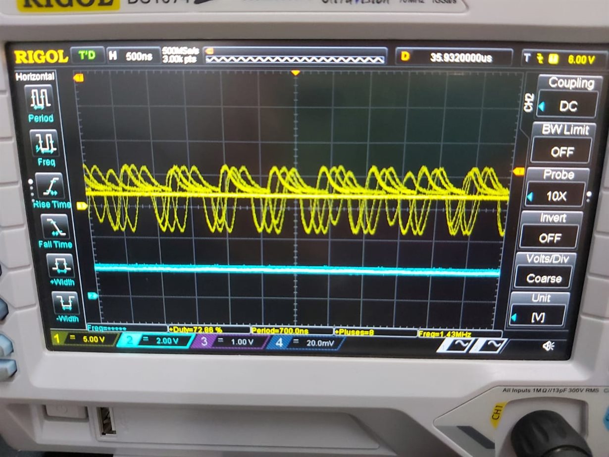
    the output waveforms are all jittery not getting any clean waveform still I have attached the waveform yellow probe attached to inductor input blue probe attached to Vout.

    Regards

    Pranav