Hello all,
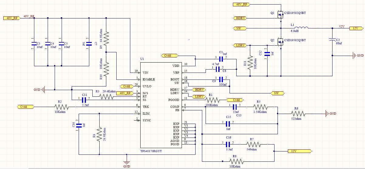
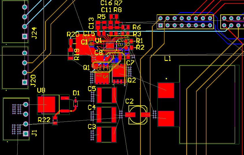
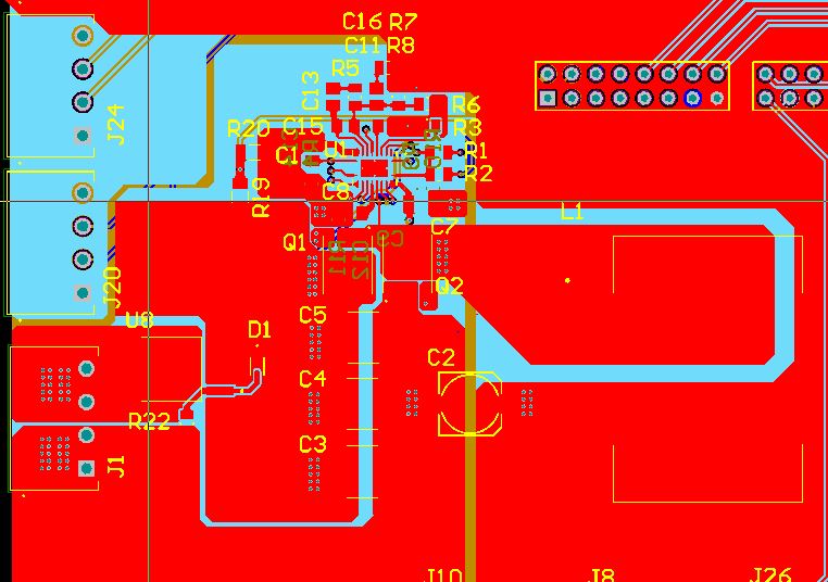
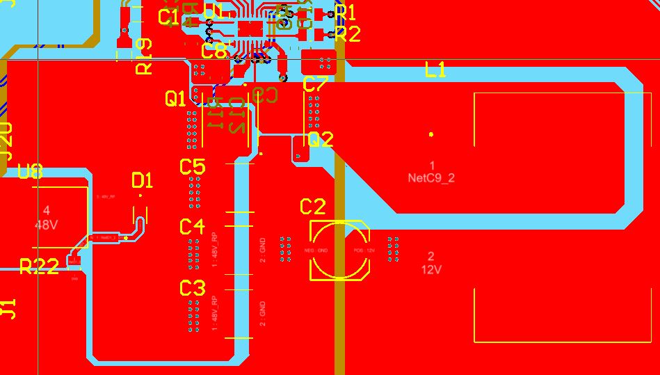
I am designing a customized board for my application. My board works on 12V and it requires 15A output current. I need to step down from 48V to 12V for my application. So, I am using TPS40170-Q1 for this application. Below attached is my schematic and PCB layout for the TPS40170-Q1 part of the board.
My design parameters are as follows:
Working frequency: 320Khz
Input filter: three 10uF capacitors of 2220(5750 metric) packing and 100Vdc rated (Manufacturer part no: C5750X7S2A106M230KB)
Output filter: SMD inductor with 6.8uH inductance, 1.68mohm dc resistance and 27.8A maximum dc current (Manufacturer part no: SER2915L-682KL)
SMD aluminum polymer capacitor with 68uF, ESR = 35mohm and 35Vdc rated (Manufacturer part no: EEH-ZA1V680XP)
CSD19502Q5BT SMD type MOSFET is used
Please help me with the design validation. (In the below-shown schematic 48V_RP is the 48V signal coming out of reverse polarity circuit.)