This thread has been locked.

If you have a related question, please click the "Ask a related question" button in the top right corner. The newly created question will be automatically linked to this question.

BQ76952: I2C Communication Failure

Part Number: BQ76952
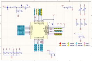
We are using & doing testing on BQ76952 on our custom board. It is powered on & REG18 is present. But when we are trying to establish I2C communication we are not getting ACK bit. we even probed it we could see NACK & we have a direct DFETOFF connected from MCU to AFE on our custom board, we asserted it we could see all FETs getting off. So it means AFE is working. But I tapped I2C from our custom Board MCU to EVM AFE, communication established successfully.
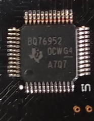
So while going though Forum I found out that same issue thread & they mentioned there was an earlier batch of this IC in which there was an I2C bug.
Please can you provide more information regarding this issue & help us with more details.
Here is the link of the similar issue in which they mentioned about I2C bug in earlier batch of the IC.
  • This is the top marking of IC - BQ76952 0CWG4 A707

  • We changed it from new batch of IC now its working.

  • Sorry to inform we are now again facing same I2C communication failure. Please help me regarding this issue. As well as REG18 is now coming out to be 0.6V.

  • Hi Pankaj,

    Something must be really wrong on the hardware if the REG18 is not reaching 1.8V. Can you share the sequence of what is being done with the board along with a schematic? 

    I suspect the device is getting damaged and you will need to replace it.

    Regards,

    Matt

  • Hi Matt,

    First we are connecting Cell Voltage sense connector which is power our AFE & then we connect Buck Power connector coming from same Battery Pack.

    Actually wrong value of REG18 is coming on our 2 boards we have some other also in there it is coming 1.8V but still I2C communication is not happening it is always giving a NACK.

    Here below I am sharing AFE Schematic Sheet.

    Please have a look

  • Hi Pankaj,

    I do not see any issue with the schematic. Are there pull-up resistors connected on another page for the I2C lines (SDA and SCL)?

  • Yes we have pull ups on other sheet & I would like to inform that our AFE started communicating because pack Voltage sense pin was not able to sense any voltage on its pin as Pack power was not connected.

    After providing Pack Sense it is communicating fine. But Now I have different questions: 

    1) While flashing & re-flashing our MCU pulls high rest_shut high & pull AFE to shutdown Mode(I am assuming), but as we are using TS2 & right now it is left floating.I don't see any voltage at TS2 pin & REG1V8 also shows 1.8V but communication doesn't happen but if I pull down TS2 manually to bring it out of shutdown & then try communication again it works. So how can we really be sure to know if AFE is in Shutdown mode.

    2) After establishing communication we are observing Cell Voltages, we over ride the cell voltage value to be as cell over Voltage value. AFE went into shutdown, so how can we know when AFE is going into shutdown & then Bring it back to normal using software without using hardware changes (Like pulling down TS2 manually or connecting charger or disconnecting Load). or is there any way that AFE tell our MCU before going to shutdown about its state.

    Kindly provide more information on this. it will be very helpful for me.

  • Hi Pankaj,

    There is an [SDM] bit in the BatteryStatus register that indicates a Shutdown is pending due to a command or a signal on the RST_SHUT pin. You can increase the time to transition to Shutdown using the Power:Shutdown:Shutdown Command Delay parameter. 

    However, you really should avoid using Shutdown if you do not have a way for the hardware to wake the device. So it is important to prevent the MCU from accidentally triggering Shutdown with the RST_SHUT pin. 

    Best regards,

    Matt

  • Hi Matt,

    I was doing my BMS Discharge Testing, discharging works good but after hitting pack under voltage it cuts off correctly. After Pack under voltage cut off we are keeping only Pre charge mosfet to be on, but when we connect charger, no current flows & there in no switching to main mosfets. Pack dose not charge.

  • Hi Pankaj,

    Have you reviewed Table 5-12 of the TRM to understand the conditions for recovering from the under-voltage protection? Have you cleared the alarm register and is the voltage above the CUV hysteresis? 

    Best regards,

    Matt

  • Hi Matt,

    I have a question that in my custom board while using only Main Charge/Discharge mosfets not the pre- mosfets, whenever I connect just Electronic load without even switching Electronic load ON our both Charge & Discharge mosfets goes OF & when I Disconnect the load they switches ON again normally. 

    we tried connecting & Disconnecting E-Load various times & both mosfets goes OFF.

    we are confuse with this behavior of AFE & While connecting it to charger we are able to charge it & both mosfets are staying ON & charging is happening.

    Kindly provide any information so that we can perform other tests.

  • little update regarding this is that in code we could see Stack voltage shutdown was initiated & as well as Fuse pin was also getting asserted even though we are not using Fuse pin in our custom board.

  • Hi Pankaj,

    Can you read all of the Safety Alert and Safety Status registers to see what is triggering the FETs to turn off? Also, read the PF Alert / PF Status registers. The default Shutdown Stack voltage is 6V, so there must be a very low voltage on the cells to trigger Shutdown.

    The Fuse status bit will go high and low if the FUSE pin is floating - you can ignore this bit or tie the FUSE pin to VSS.

    Best regards,

    Matt

  • Yes it is at default shutdown stack voltage but then the question is can we see because of what stack shutdown was initiated because I have probed the 16 cell voltage it was not at all dropping down when connecting the E-Load.

    & is there any way to ignore stack voltage shutdown.

  • One more update that we can not see any difference in Safety Alert and Safety Status registers & PF Alert / PF Status registers. 

  • The Shutdown Stack Voltage can be changed to zero - this will disable that feature. But it is important to debug why the stack voltage would see a low voltage.