This thread has been locked.

If you have a related question, please click the "Ask a related question" button in the top right corner. The newly created question will be automatically linked to this question.

BQ25616: The Current Limit doesn't Work, Please help

Part Number: BQ25616
Other Parts Discussed in Thread: BQ25606,

Dear All,

I designed the single cell battery charger. My power source is 5V, 3A. I let the float VSET, ILIM = 205 Ohm (the input current limit is 2.5 A) and ICHG = 649 Ohm (the charge current limit is 1A). I monitor the SYS pin voltage is 4.2V with a maximum load of 470 mA. If I increase the load a little higher, the SYS pin voltage will decrease which means it could not handle the load greater than 470 m 
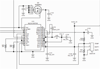
A. Based on its design, it should be higher. I don't know what goes wrong in my conception. I hope somebody can help highlight the problem.

Thanks

  • Hi,

    What are your test conditions such as VBUS (voltage at VBUS pin), IVBUS, VBAT (voltage at BAT pin), IBAT, VSYS, ISYS when you think the operation is abnormal?

    Thanks,

    Ning.

  • Dear Ning,

    POWER SUPPLY 5V, 3A, VBUS = 5V, VBAT= 4.2V, VSYS = 4.2V. I didn't install the battery but add 10K between TS to GND (simulate the thermistor). I added the load to VSYS.
    This is the result:
    The load at VSYS is 8.33 OHM (3x25 OHM in parallel) The power supply current is 460 mA, VBUS = 4.95V, VSYS = 4.2V, VBAT = 4.2V.
    The load at VSYS is 6.25 OHM (4x25 OHM in parallel) The power supply current is 480 mA, VBUS = 4.95V, VSYS = 3.7V, VBAT = 3.7V.
    The load at VSYS is 5 OHM (5x25 OHM in parallel) The power supply current is 480 mA, VBUS = 4.95V, VSYS = 3.3V, VBAT = 0V.
    The abnormal is the power supply Current staying the same at 480 mA. The normal is when VSYS = 3.3v the VBAT = 0V.
    I double check the design many times, and it corrected.
    Sincerely,

    Luke Nguyen

  • Dear Ning,
    I got few more graph for you. Yellow is VSYS and BLUE is the SW pins.
    IMG_0182: The VSYS load 12.5 OHMS (2x 25 OHM in parallel)
    IMG_0183: The VSYS load 8.33 OHMS (3x 25 OHM in parallel)
    IMG_0184: The VSYS load 6.25 OHMS (4x 25 OHM in parallel)
    IMG_0185: The VSYS load 5 OHMS (4x 25 OHM in parallel)
    I saw the duty cycle has changed. Is this a problem?
    Sincerely,
    Luke Nguyen
  • Luke,

    Please visit https://e2e.ti.com/support/power-management/f/196/t/890626 for BQ25606: Schematic Review and PCB Layout Design Tips. Additional Information including FAQs is available http://www.ti.com/lit/an/slva924/slva924.pdf Designing A Standalone Single Cell 3-A Charger with the bq25606. FAQ "When battery is not connected, that is, BAT pin is floating, why does the STAT pin blink?" BQ25616 is similar to BQ25606.

    If the charger is powered up without the battery, VSYS will start from 0V and may stuck in 200mA IINDPM if SYS tries to pull too much current during the start-up. Referring to the d/s, the IINDPM is set to 200mA if VSYS is less than 2.2V.

    Do not apply more than 200mA load at VSYS when VSYS<2.2V.

    Thanks,

    NIng.

  • Dear Ning T,

    First of all! Thank you for your assistance.

    We've figured out the problem and I'm going to share it with you. Pins 3 (D) and 4 (D-) attached to the MCU I/O port. These pins are our support in the future used. However, the MCU was not powered on, so the I/O port pulls them down and the BQ25616 did not like it. Once these two pins are isolated, the charger circuit functions as a design.