


Hello, TI expert.
I am testing the LLC block by applying UCC25600
Spec is shown in the table below. (Max 360V / 3A output)

When operating according to the specifications of the current circuit diagram, the LLC output current ripple (Ip-p) is measured about 5.65A.
We want to adjust the transformer and resonant cap specifications to reduce current ripple.
Q1) What can be done to reduce the output current ripple?
Q2) Besides reducing the output current ripple, is there anything else that needs to be modified for the stability of the circuit?
The current LLC specifications are as follows:
1) Lp(1st inductance)
Trans(T302, T303) : 36uH (In the circuit diagram, two transformers are connected in series, Lp: 72uH)
2) Lr(Leakage inductance) :
Trans(T302, T303): 7uH (In the circuit diagram, two transformers are connected in series, Lr: 14uH)
Leakage Trans(T301) : 10uH
3) Number of turns
Trans(T302, T303) : 1st 11turns / 2nd 30turns (In the circuit diagram, the first is 22 turns in series and the second is 30 turns in parallel.)
4) Resonance cap : 94nF
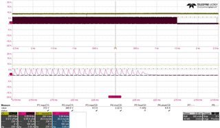
Below are the voltage and current waveforms between LLC FET Drain and Source and the LLC output current waveform. Please check
-. LLC FET Drain-Source (CH1 : D-S voltage / CH2 : Drain current)
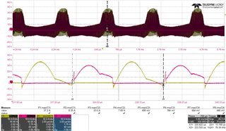
-. LLC output current
The circuit diagram and waveform are attached, so please check it.
Thank you.
