This thread has been locked.

If you have a related question, please click the "Ask a related question" button in the top right corner. The newly created question will be automatically linked to this question.

UC3846: Duty cycle of UC3846

Part Number: UC3846

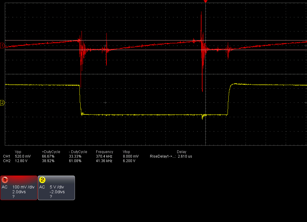
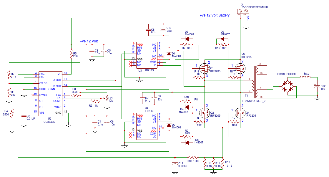
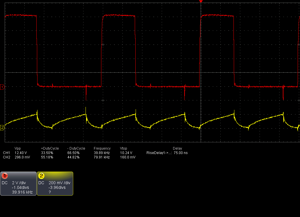
I am testing UC3846 duty cycle at output with rotating potentiometer (by varying voltage) at EA pin EA(-). My maximum duty cycle is 38%. I am getting gradual change from 10% to 26% in duty cycle by rotating potentiometer at EA(-) pin. But after 26% it jumps to 38% directly. I changed the potentiometers & its values but the result is the same. Where is the mistake? Please help.

Thanks.

-Satyavijay

  • Hi Satyavijay,

    Thanks for your interest in UC3846. Do you have anything connected to the CS+ and CS- pins? Could you post a schematic of your circuit?

    Best Regards,
    Ben Lough
  • Thanks for support.

    Between CS+ and CS- there are three resistors of value 0.16 ohm each. Voltage at pin1 is 0.5V. EA+ pin at 5.1V. I am testing with no load.

    At present I have no scan copy of my schematic despite above information if needed it I will scan it and  post.

    Regards.

  • Hi Satyavijay,

    Could you use an oscilloscope to check the waveform of the CS+ pin? You should see something that resembles a ramp signal. A copy of your schematic would be helpful. If you do not want to post it publicly, you can email me at ben.lough@ti.com.

    Best Regards,
    Ben Lough
  • Thanks Sir. Oscilloscope image is attached for your reference. I will post schematic after scanning.

    Regards.

  • Hi Satyavijay,

    Thank you for the additional information. Is your design intended to be open loop? If yes, I would suggest operating the controller in a slave configuration. There is an example of this on page 13 of the UC3846 datasheet. www.ti.com/.../uc2846m.pdf. Tie E/A- to gnd and E/A+ to Vref. To adjust the duty cycle, vary the voltage at the COMP pin.

    Best Regards,
    Ben Lough
  • Thanks.
    My design will be closed loop. This testing is for just to see how chip works. I did not get the detailed working of EA, CS comparator and internal latch in combination. Where can I get this information ?
    My thinking is - up to peak current ramp voltage duty cycle is gradually changing and after that it jumps to maximum duty cycle. Please confirm.
    Regards.
  • Hi Satyavijay,

    The voltage across the current sense resistor is internally amplified with a gain of 3. The output of the error amplifier (the COMP pin) is shifted down by 0.5V and is compared to the amplified current sense signal to determine duty cycle. There should not be a jump in the duty cycle.

    For testing, I suggest configuring the device for slave mode if you are looking to adjust duty cycle.I also suggest checking that the current signal is not tripping the programmed current limit of pin 1. You can calculate the current limit using the equation found in section 8.2.2.4 of the datasheet.

    Best Regards,
    Ben Lough
  • As per your suggestion I will test in slave mode.

    Thanks.

  • After various tries I found the solution and now duty cycle is not jumping directly to 38% from 26%. I have given a little load and tested. Oscilloscope screen shots are attached.

    Thanks you very much for your prompt support.

    Satyavijay.