[FAQ] AM625 / AM623 / AM620-Q1 / AM625-Q1 / AM62Ax / AM62D-Q1 / AM62Px / AM64x / AM243x (ALV, ALX) Design Recommendations / Custom board hardware design - Processor Reset inputs, Reset Status Outputs and Connection Recommendations

Part Number: AM625
Other Parts Discussed in Thread: AM62P, AM62D-Q1, TPS65224-Q1, AM6442

Tool/software:

HI TI experts,

I have queries related to supported reset inputs and reset status outputs 

Supported Reset inputs 

Recommended connections for Reset inputs 

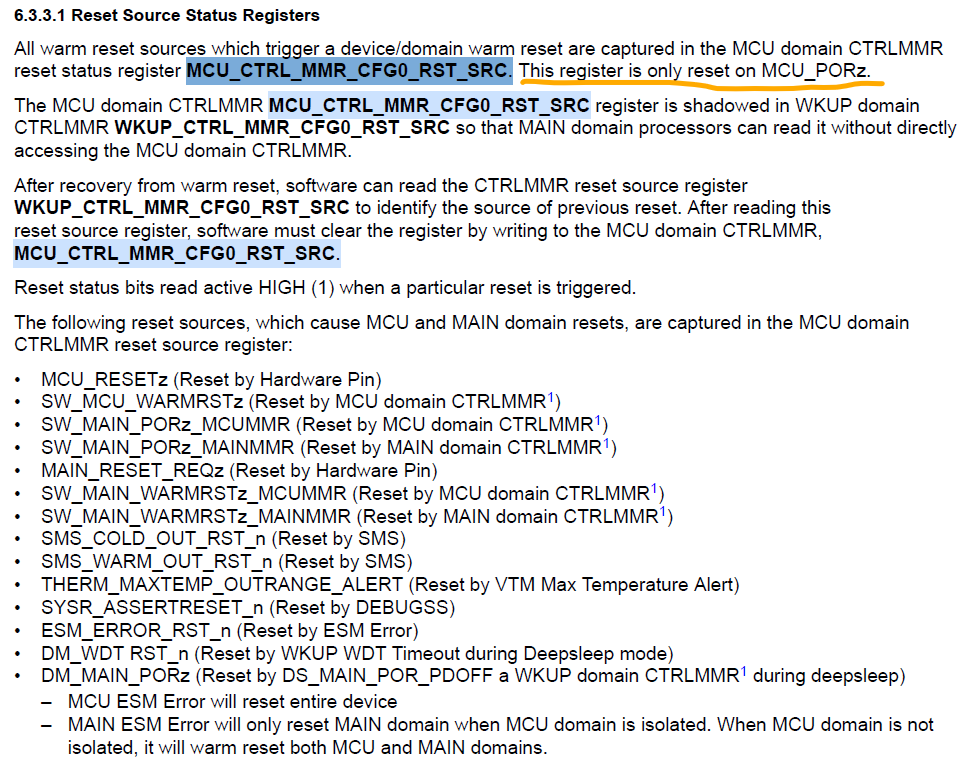
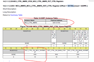
Supported Reset Status outputs

Recommended connections for Reset Status outputs

  • HI Board designers, 

    Please refer below.

    Supported Reset input and output signals

    AM64x

    AM243x (ALV/ALX)

    AM625

    AM62A

    AM62P

    Connection recommendations 

    AM64x/AM243x/AM62x/AM62Px/AM62Ax/AM62D-Q1 

    MCU_PORz

    Leaving MCU_PORz unconnected is not allowed or recommended. Connect to a valid reset input with minimum slew. use a 22-pF glitch filter.

    Warm reset input

    Reset Status output

    Add a pulldown to hold the attached device in reset during supply ramp.

    When not connected to any attached device add a TP for testing.

    Regards,

    Sreenivasa

  • Hi Board designers

    Please refer below inputs for MCU_PORz, RESET_REQz and MCU_RESETz reset inputs slew rate requirements:

    The Electrical Characteristics tables defines capabilities of a specific IO cell. It does not define a how the IO is configured to operate. You need to reference the Pin Attributes table to understand how the IO associated with each pin is configured to operate. For example, the AM64x RESETSTATz signal function is implemented such that it is "Off / Low / Off" while MCU_PORz is asserted and "Off / SS / Off" after MCU_PORz has been de-asserted. This indicates the input buffer associated with the RESETSTATz pin is turned off during and after reset. The output buffer associated with the RESETSTATz pin is enabled during and after reset, where the output is actively driven low during reset and controlled by the reset subsystem after reset. The internal pull resistors associated with the RESETSTATz pin are turned off during and after reset.

    In summary the RESETSTATz pin is an always enabled output only pin, where Vol, Voh, Iol, and Ioh are the only parameters defined in the LVCMOS Electrical Characteristics table that applies to the LVCMOS IO that is being used to implement the RESETSTATz pin.

    TPS65224-Q1 nRSTOUT for MCU_PORz

    Please keep in mind the AM62Ax device requires the MCU_PORz input to have a maximum rise/fall time of 1000ns. This may be difficult to achieve with a pull-up on a signal sourced from an open-drain output buffer. You may need to buffer the open-drain signal with a push-pull buffer that has hysteresis on its input to ensure the AM62Ax device never receives a short reset pulse that violates the minimum pulse duration defined in the "MCU_PORz Timing Requirements" table. For example, it may be possible for noise to couple on the slow rising open-drain signal just as it crosses the input buffer threshold which could cause a short glitch on the reset signal. Normal device operation could be compromised if this occurs.

    See the "Input Slew Rate" parameter in the "Fail-Safe Reset (FS RESET) Electrical Characteristics" table.

    The MCU_PORz input is the only input on the AM62x device that is fail-safe and 3.3v tolerant. Therefore, you can pull the MCU_PORz signal to 1.8V or 3.3V.

    See the "Steady-state max voltage at all fail-safe IO pins" parameter for MCU_PORz in the "Absolute Maximum Ratings" table.

     important point about the MCU_PORz input slew rate. It is very easy for noise to couple on slow rising signals such that it creates non-monotonic transitions. Your MCU_PORz reset source needs to be monotonic to prevent the chance of creating glitches on internal reset as it transitions through the input buffer switching threshold. A faster slew rate on the MCU_PORz will increase your system noise immunity. The min slew rate defined in the AM62Ax datasheet is acceptable to the AM62A device but may not be acceptable for your system noise immunity requirements.

     We define a minimum slew rate in the SOC datasheet for inputs and this creates a maximum rise time requirement. The rise/fall time for the reset signal must be less than 1000ns, not greater than 1000ns. To ensure your design meets this requirement, you may need to use a buffer between the PMIC and SOC or select a pull-up resistor value that is strong enough to charge your PCB parasitic capacitance and the SOC input capacitance in less than 1000ns. A rise significantly faster than 1000ns is preferred to minimize the potential of noise coupling to the reset signal.

     We have discussed on the cold reset input MCU_PORz having internal hysteresis enabled and the need to apply signal with Min slew or use a discrete push pull buffer to avoid glitching of the internal reset.

    Does the MCU_RESETz and RESET_REQz warm reset inputs implement similar hysteresis and the above recommendations be valid for these warm reset inputs.

    The real concern with reset is creating a short assertion pulse.  The reset is asynchronously applied to all flops in the device.  However, it takes some time for the reset to propagate to all of the flops.  Creating a short assertion pulse could allow some flops to be reset and other flops not to be reset if the assertion pulse width is less than the time it takes for the asynchronous reset to propagate to all flops.  If this happens, the unexpected start condition could cause state machines to do unpredictable things.  So yes, the concern is that a slow transition through the input buffers switching threshold along with noise in the system could generate a glitch on the internal reset signal, which creates a shorter than expected reset assertion pulse.

    To answer the first part of your next question, you simply need to look in the datasheet.


    For the second part of your question, the datasheet defines the same minimum active pulse width of 1200ns for both MCU_RESETz and RESET_REQz inputs that was defined for MCU_PORz.  Therefore, I think these reset inputs have the same requirements as MCU_PORz.

     The Hysteresis in enabled for the IO that support hysteresis using PADCONFIG register. the hysteresis is enabled by default.

    Regards,

    Sreenivasa

  • Hi Board designers,

    (+) [FAQ] AM625 / AM623 / AM620-Q1 / AM625-Q1 / AM625SIP: MCU_PORz input slew rate - Processors forum - Processors - TI E2E support forums

    Usually add RC filter on RESET signal to anti noise, but the slew rate requirement of RESET signal on AM62x datasheet is quite sharp, on customer board it is about 10V-100V/ms, can it meet AM62x reset requirement, if not please help to explain the basic mechanism. 

    There can be long-term reliability issues associate with the input buffer if the applied signal spends too much time in the voltage region between VIHSS and VILSS. The maximum transition time allowed is 1000ns. I recommend driving the reset input with a push-pull buffer that produces a signal transition rate that is faster than 10ns to eliminate the risk of noise coupling into the signal as it transitions through the input buffer switching threshold.

    A 22 pF glitch filter is recommended at the input of MCU_PORz

     another important point about the MCU_PORz input slew rate. It is very easy for noise to couple on slow rising signals such that it creates non-monotonic transitions. Your MCU_PORz reset source needs to be monotonic to prevent the chance of creating glitches on internal reset as it transitions through the input buffer switching threshold. A faster slew rate on the MCU_PORz will increase your system noise immunity. The min slew rate defined in the AM625 datasheet is acceptable to the AM625 device but may not be acceptable for your system noise immunity requirements.

    Please keep in mind the AM62x device requires the MCU_PORz input to have a maximum rise/fall time of 1000ns. This may be difficult to achieve with a pull-up on a signal sourced from an open-drain output buffer. You may need to buffer the open-drain signal with a push-pull buffer that has hysteresis on its input to ensure the AM62x device never receives a short reset pulse that violates the minimum pulse duration defined in the "MCU_PORz Timing Requirements" table. For example, it may be possible for noise to couple on the slow rising open-drain signal just as it crosses the input buffer threshold which could cause a short glitch on the reset signal. Normal device operation could be compromised if this occurs.

    See the "Input Slew Rate" parameter in the "Fail-Safe Reset (FS RESET) Electrical Characteristics" table.

    The MCU_PORz input is the only input on the AM62x device that is fail-safe and 3.3v tolerant. Therefore, you can pull the MCU_PORz signal to 1.8V or 3.3V.

    See the "Steady-state max voltage at all fail-safe IO pins" parameter for MCU_PORz in the "Absolute Maximum Ratings" table.

    Regards,

    Sreenivasa

  • Hi Board designers,

    FAQs for reference

    https://e2e.ti.com/support/processors-group/processors/f/processors-forum/999468/faq-am6442-reset-circuit-review-for-am6442

    1. Is there any problem that is expected when simplified with POWER-ON and Cold RESET as above circuit?

    This is not adequate for MCU_PORz.  Please review the reset section 7.10.3.1 and figure 7-3 of the datasheet.  MCU_PORz should be low throughout the power up sequencing and remain low for 9.5ms.  

    Regards,

    Sreenivasa

  • Hi Board designers,

    Use of RESETSTATz for resetting attached devices:

    AM620-Q1: reset of eMMC circuit on EVM

    Customer is asking for if our AM62x EVM design for resetting eMMC using an AND gate (see schematics) is a solution we would also recommend for series production ... or do we consider that as a functional demo only?

    The AND gate produces an eMMC device reset when either RESETSTATZ is asserted low or the GPIO connected to GPIO_eMMC_RSTn is asserted low. The RESETSTATZ signal will be asserted when the AM62x receives a cold reset or a warm reset. This signal is needed to ensure the eMMC device is returned to its initial operating state any time the AM62x device is reset. The GPIO_eMMC_RSTn is provided to allow the eMMC software driver to reset the eMMC device in case it wants to reset the entire eMMC subsystem. 

    You will need to check the eMMC software driver you plan to use to know if this function is available and to understand how you tell it which GPIO was used for this function.

    (+) AM623: AM623: Question on SK-AM62 Design - Processors forum - Processors - TI E2E support forums

     U58 is an AND gate, so the output is only high when inputs 1 and 2 are high, otherwise it is low. However, there is also an up pull on the RST side, so the RST side is always high, right?

             Please help explain, thank you

  • Hi Board designers,

    Additional input on performing cold reset:

    AM62A RESET_REQz

    I have customer using one of the GPIO connected to RESET_REQz to perform a warm reset.
    The RESET_REQz has a pullup of 10K
    I see the below timing requirement in the data sheet
    RST15 tw(RESET_REQzL) (1) Pulse Width, RESET_REQz active (low) 1200 ns

    I am trying to understand the internal behavior of the warm reset

    Is there a concern with the above customer approach.

    Is there a timing (time taken) for the GPIOs to be reset after the warm reset input is asserted. (will the internal reset wait for 1200ns before initiating the reset).

    So they are connecting an AM62A GPIO wrapped back around to the RESET_REQz? I would not recommend this. The signal timing would not work as the GPIO module would quit driving too early.

    And anyway they can accomplish the same thing using SW_MAIN_WARMRSTz in WKUP_CTRL_MMRx_RST_CTRL.

    Regards,

    Sreenivasa

  • Hi Board designers,

    Inputs related to reset implementation

    (+) PROCESSOR-SDK-AM62X: Uboot stage reset not working - Processors forum - Processors - TI E2E support forums

    reset" @u-boot.

    "reboot" @kernel

    Regards,

    Sreenivasa

  • Hi Board designers,

    FYI for MCU_RESETSTATz, PORz_OUT and RESETSTATz

    All three outputs are driven low by AM64x as soon as power is valid. This is assuming your design asserts MCU_PORz low as expected, before the supplies begin to ramp, and continue to holding MCU_PORz low until the reference clock source is stable. The reset outputs in question will remain in a driven low state until MCU_PORz is released, where the control of these IOs are handed over to the respective reset subsystem. 

    Note: The state of AM64x pins are not defined as power ramps. For example, AM64x could even drive these pins high while the supplies are ramping. If this occurs, an external pull-down is not going to hold these reset outputs low.

    There is also a chance these IOs will be undriven during power ramp. An external pull-down may hold the signals low in this case if none of the attached devices have internal pull-up resistors. However, there is a good chance attached devices will have an internal pull-up which means the signal could be pulled to a mid-supply voltage if there is an external pull-down.

    These pins are implemented with standard IO cells configured to operate as outputs.  However, the input buffer may or may not be disabled during power ramp.  If they are enabled, the input buffer would experience shoot through current that flows from the IO's VDD supply to VSS when a mid-supply voltage is applied to its input. This is not a desired state for the IOs or any other input buffer attached to these signals. 

    Regards,

    Sreenivasa

  • Hi Board designers,

    Query related to MCU_PORz

    MCU_PORz toggle without power cycling (AM644x)

    I have customer performing the following  on the MCU_PORz (main, mcu domain cold reset input) pin

    • Using a push button as reset input
    • Using another FPGA or MCU as reset pin

    I suspect this should be Ok but wanted to check if there is any requirement to power cycle the SOC to assert the MCU_PORz input.

    Using a push button is likely to be problematic since there is a good chance contact bounce will produce a low pulse that violates the min reset pulse of 1200ns defined by parameter RST3.

    The recommendation is to consider using a reset supervisor that is able to debounce the switch and hold the signal low long enough to meet the 1200ns requirement.

    Adding a capacitor at the input of MCU_PORz (>22pF) is not recommended because it would cause the signal to rise/fall too slow for the cold reset inpu

     If there is a MCU or FPGA connected to the same signal, the attached device may operate as an input and open-drain output (similar to how our warm reset pin works on AM335x).  It may be able to detect any falling edge created by the pushbutton switch or any other device that can pull the signal low, and apply a debounce period where it holds the signal low long enough for the switch bounce to end, and long enough to meet the 1200ns requirement.

     (+) AM62A7-Q1: MCU_PORz slew rate - Processors forum - Processors - TI E2E support forums

    Regards,

    Sreenivasa


  • Hi Board designers,

    Inputs related to Main/MCU domain

    e2e.ti.com/.../4981064

    If I want the MCU domain and the MAIN domain to be powered independently, without affecting each other. Do you only need to power VDDS_OSC, VDDSHV_MCU, VMON_1P8_MCU and VMON_3P3_MCU independently? Does the starting sequence of the power supply change? What is the impact? Do you have relevant precautions and documents?

    This is not an option for AM64x. All power rails must be powered, and they must be sequenced as defined in the datasheet.

    The concept of MCU and Main only applies to internal device functions and processor domains. The device does not have separate MCU and Main power domains.

    The MCU domain is considered when low latency real time functions are required to be implemented. The MCU which is part of the MCU domain is used to support safety requirements. MCU with freedom from interference (FFI) is primarily used for monitoring and diagnostics, and a number of general and I/O protocols,

    Functional Safety Support for Arm®-based Microcontrollers and Processors
    https://www.ti.com/lit/wp/spradf6a/spradf6a.pdf

     https://e2e.ti.com/support/processors-group/processors---internal/f/processors---internal-forum/1488068/audio-am62d-evm-regarding-mcu-with-ffi 

     https://e2e.ti.com/support/processors-group/processors/f/processors-forum/1468969/am620-q1-is-reset-isolation-for-mcu-domain-is-so-called-ffi-freedom-from-interference 

    Please limit AUTOSAR image to run code from only the internal SRAM. M4 performance executing from DDR will have significant latency. M4 access to DDR is currently measured to be >200 cycles. hence we do not recommend using external memory for AutoSAR implementation.
    There is no L3 cache on MCU interconnect on AM62.

     https://e2e.ti.com/support/processors-group/processors/f/processors-forum/1503713/am620-q1-what-s-the-variant-use-case-for-ffi/5838678 

     https://e2e.ti.com/support/processors-group/processors/f/processors-forum/1505285/am620-q1-concept-clarification-for-mcu-only-mode-base-on-sdk-11-0 

    (+) AM620-Q1: What's the variant use case for FFI. - Processors forum - Processors - TI E2E support forums

    FFI can be tricky because it highly depends on the safety architecture at the system level and the specific use case that the device is used in. 

    (1) If FFI (Reset Isolation) is "enable", we can say AM62 works in ASIL-B (Y/N?). [Alex] Yes, typically enabling the reset isolation will allow for full ASIL-B claims.

    (2) If we allow "Partially Isolated", there should be two case,

    (2a) Main domain can access MCU domain peripherals or register, main core even can "warn reset" mcu core by internal register setting. Base on this condition, we cannot say AM62 match ASIL-B requirement (Y/N?) [Alex] Yes, typically you don't want non-safety IPs/devices to have access to safety ones. There may be exceptions to this depending on the safety use-case.

    (2b) MCU domain can access Main domain peripherals or register, mcu core can "warn reset" main core by internal register setting. Base on this condition, we also cannot say AM62 match ASIL-B requirement (Y/N?) [Alex] Yes, safety IPs/device can have access to non-safety or lower safety ones. This happens frequently in safety use cases.

    (3) Once you enable "Partially Isolated", it means you also "open" part of memory region or register between main/mcu domain, this is kind of potential risk w/ software FFI. Base on this condition, we can not say AM62 match ASIL-B requirement  (Y/N?) [Alex] Yes, your understanding is correct. The biggest risk with opening the region between the main and mcu is that you can no longer ensure that unsafe software has access to the safety related configurations or functions.

    These were all very good questions. Thank you for thinking in detail about the consequences of FFI on the safety use-case. 

    ① What is the difference between MPU and Firewall? Here's my understanding:
    MPU: Prevents interference of tasks running on the R5 core. Firewall: Restricts access of devices via the CBASS interface.

    Yes

    ② In our system, all software on the MCU R5 is considered ASIL. Is MPU configuration necessary?
    Based on the concept in question ①,
    I am considering that MPU configuration is not necessary.
    If it is necessary, I would like to see a use case.

     https://e2e.ti.com/support/processors-group/processors/f/processors-forum/1376181/sk-am62a-lp-how-enable-and-check-safety-features-on-mcu-r5f-core 

    (+) AM67A: MCU_PORz or RESETSTATz to control bootmode buffers - Processors forum - Processors - TI E2E support forums

    RESETSTATz is the preferred reset output for bootmode buffer.  It is released later in the reset sequence, which helps to ensure correct value on the pints at latching.

    Regards,

    Sreenivasa

  • Hi Board designers,

    FYI, inputs related to RESET (input/output)

    (+) AM67A: Purpose of the reset lines and reset outputs - Processors forum - Processors - TI E2E support forums

    MCU_PORZ:  MCU and Main Domain cold reset.  This is the power-on reset for the MCU/entire device and is required.

    MCU_RESETZ:  MCU and Main Domain warm reset  This is the warm reset request for the MCU/entire device, optional. Pull-up if not used

    RESET_REQZ:  Main Domain external warm reset request input.  This is main domain warm reset request, optional.  Pull-up if not used

    Cold (power on reset) resets the entire device (all registers).  Warm reset reset most of the registers, but does not reset everything.  See TRM for definitions of which resets are NOT reset with warm reset.   Support for separate warm reset is optional.

    PORZ_OUT:  Power-On reset status output, simply buffered version of MCU_PORz input. 

    MCU_RESETSTATZ:  MCU Domain warm reset status output.  This the reset output of the MCU/entire device.  Is asserted for both external reset (MCU_PORz) and internal reset conditions (in the mcu domain).

    RESETSTATZ:  Main Domain warm reset status output, this reset output of the main domain, asserted for both external reset (MCU_PORz) and internal reset conditions (in the main domain).

    Which reset output to you for peripherals is design dependent.  If you want peripherals to reset only at power-up, the PORz_OUT.  If you want peripherals to reset at power-up and any time a internal processor reset is issued - then RESETSTATz.

    Regards,

    Sreenivasa

  • Hi Board designers,

    FYI

    RESETSTATz during reboot (software warm reset)

     after each reboot, RESETSTATz will be pulled low for 220 µs, and eMMC_RSTn is affected by the action of RESETSTATz.

    Regards,

    Sreenivasa