Other Parts Discussed in Thread: TMS470R1B1M
Dear Sir
I have 3 questions:
The first one:
I implemented a real time clock with the RTI module and the clock comes from OSCIN directly. here is my code:
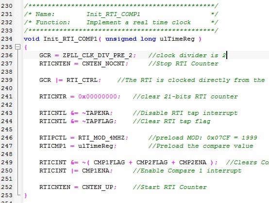
here is interrupt subroutine:
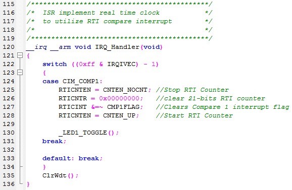
the code works very well, but if I changed line236 to GCR=ZPLL_CLK_DIV_PRE_1
it does not work, in other word, it does not work when fsysclk=fvco. the the RTICNTR continue to count
the pulses, no CMP1FLAG set when RTICNTR is equal to RTICMP1, please tell me the reason.
The second
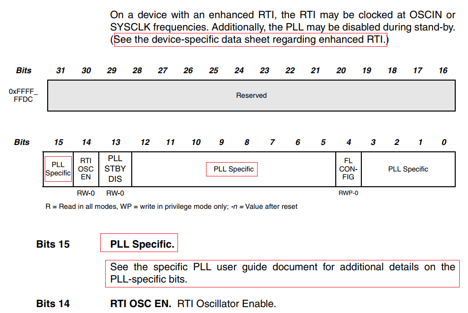
the document always said "PLL Specific" and "the device-specific data sheet", where do I get it?
The third
Some registers are not in accordance with iotms470r1b1m.h and tms470r1B1m_bit_definitions.h
such as I can't find GCR_N, GLBCTRL in the head files, I can find GCR olny. is the TI has latest documents
for the this MCU?