This thread has been locked.

If you have a related question, please click the "Ask a related question" button in the top right corner. The newly created question will be automatically linked to this question.

AM4378: Cortex-A9 frequency

Part Number: AM4378

Hi team,


On the datasheet Table 3-1, AM4378 ARM Cortex-A9 is specified as 800MHz/1000MHz.


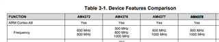
Does that mean other frequency, for example 600MHz or 300MHz, is not supported?

Is it possible to operate AM4378 with 600MHz or 300MHz? If yes. Could you share how?


Best regards,

Kurumi

  • Can someone please answer this?

    Thanks!

  • Hi Kurumi,

    The contents of Table 3-1 that you are highlighting show the maximum supported frequency of each of these devices. AM4378 is up to 800MH/1000MHz.

    To lower the frequency, please see the examples and procedure in section 6.6.9.1 of the TRM, 'Configuring the MPU PLL':

    6.6.9.1 Configuring the MPU PLL
    The following steps detail how to configure the MPU PLL.
    1. Switch PLL to bypass mode by setting CM_CLKMODE_DPLL_MPU.DPLL_EN to 0x4.
    2. Wait for CM_IDLEST_DPLL_MPU.ST_MN_BYPASS = 1 to ensure PLL is in bypass
    (CM_IDLEST_DPLL_MPU.ST_DPLL_CLK should also change to 0 to denote the PLL is unlocked).
    3. Configure Multiply and Divide values by setting CM_CLKSEL_DPLL_MPU.DPLL_MULT and
    DPLL_DIV to the desired values.
    4. Configure M2 divider by setting CM_DIV_M2_DPLL_MPU.DPLL_CLKOUT_DIV to the desired value.
    5. Switch over to lock mode by setting CM_CLKMODE_DPLL_MPU.DPLL_EN to 0x7.
    6. Wait for CM_IDLEST_DPLL_MPU.ST_DPLL_CLK = 1 to ensure PLL is locked
    (CM_IDLEST_DPLL_MPU.ST_MN_BYPASS should also change to 0 to denote the PLL is out of
    bypass mode).
    Note: M2 divider can also be changed on-the-fly (ie., there is no need to put the PLL in bypass and back
    to lock mode). After changing CM_DIV_M2_DPLL_MPU.DPLL_CLKOUT_DIV, check
    CM_DIV_M2_DPLL_MPU.DPLL_CLKOUT_DIVCHACK for a toggle (a change from 0 to 1 or 1 to 0) to see
    if the change was acknowledged by the PLL.

    ...

    For example:
    For a frequency for MPU, say 600 MHz, the ADPLLS is configured (PLL locked at 1200 MHz and M2
    Divider =1) so as to expect CLKOUT = 600 MHz .
    The ULOWCLKEN input from a programmable PRCM register selects whether CLKINP or CLKINPULOW
    is the bypass clock source. This is a glitch free switch. When CLKINP is selected it is sourced through the
    ADPLLS 1/(N2+1) divider. The PRCM register defaults to 0 on power-up to select the CLKINP source.
    The CLKINPULOW input may be sourced from the CORE_CLKOUTM6 from the Core PLL, or
    PER_CLKOUTM2 from the Per PLL. These PLL output clocks can be used as alternate clock sources in
    low power active use cases for the MPU Subsystem clock when the PLL is in bypass mode.

    Regards,

    Colin

  • Hi Colin,

    Thank you so much for answering, and also sharing example case.

    Best regards,

    Kurumi