This thread has been locked.

If you have a related question, please click the "Ask a related question" button in the top right corner. The newly created question will be automatically linked to this question.

AM4378: Intermediate potential

Part Number: AM4378

Hi Support Team,

I have received a question from my customer as follows.


*Customer question*
When an eMMC is connected to MMC1 of the CPU, there is a possibility
that an intermediate potential is generated by the internal pull-down (10.58k to 34.61kΩ),
external pull-up resistor (10kΩ) and internal pull-up resistor (10k to 150kΩ) of eMMC
during CPU reset (and immediately after reset release). Is this a problem?

The following is an explanation of the above conditions.

Pull-down resistors inside the CPU
AM437x Technical Reference Manual "5.2.6.5.8 Pins Used" states that
dat0-3 should be assigned to gpmc_ad8, gpmc_ad9, gpmc_ad10 and gpmc_ad11 when Booting MMC1.

Checking Table 4-10, Pin Attributes in the datasheet, gpmc_ad8, gpmc_ad9, gpmc_ad10,
and gpmc_ad11 have BALL RESET STATE and BALL RESET REL. STATE set to "L" and are pulled down
internally.
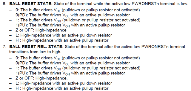


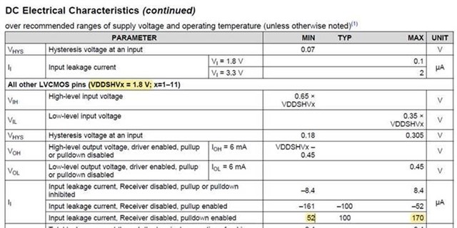
-The pull-down resistor values inside the CPU are calculated as follows.

All other LVCMOS pins (VDDSHVx = 1.8 ) with internal resistance valid for Pulldown
VDDSHVx = 1.8
Internal resistance Min. = 1.8V/170μA = 10.58kΩ
Internal resistance Max. = 1.8V/52μA = 34.61kΩ

-External pull-up resistors

Checking the schematic checklist, there is a section "2.6 MMC" that says
- When connecting a device (card or eMMC), include 10k pullups on RST#, CMD, and all DAT signals.
It is recommended to use external pullups on 10kΩ.
In addition, the JEDEC standard (JESD84-B50) "10.3.4 Bus signal line load"
also lists an external pull-up resistor of 10 to 100kΩ as a requirement for DAT1-7 of eMMC.

-Internal pull-up resistor of eMMC

JEDEC standard (JESD84-B50), "10.3.4 Bus signal line load" states
Internal pull up resistance DAT1-DAT7 is described as 10k to 150kΩ.


If you have unclear points, please let me know.

Best regards,
Kanae

  • This is a valid concern. Applying a mid-supply potential to any CMOS input buffer that is enabled will partially turn on both p-channel and n-channels in the input buffer. This causes shoot-through current to flow from the IO supply to ground. This shoot-through current could damage the input buffer if the condition remains for extended periods of time. Therefore, it is important for the system design to turn off any conflicting internal pulls as soon as possible.

    Based on the register values provided in the table above, ROM code appears to be turning off the internal pulls before it begins the boot process. So this concern is already being addressed by the eMMC boot ROM code. This could be a problem if a eMMC device is connected as described above and the eMMC boot ROM code never executes. Your system software would need to take care of this if you select a different boot mode and the ROM code never turns off the pull-downs.

    Regards,
    Paul

  • Hi Paul,

    Thank you for your reply.
    I will share it with my customer.

    Best regards,
    Kanae

  • Hi Paul,

    Here is an additional question from my customer.

    You replied that ”ROM code appears to be turning off the internal pulls before it begins the boot process,
    but is there any problem with the intermediate potential during the reset period?

    Best regards,
    Kanae

  • Hi Paul,

    I would like to confirm the above question.
    Am I correct in my understanding that the intermediate potential
    is acceptable for a very small amount of time during reset,
    as JJD answered on the following site?

    e2e.ti.com/.../4038650

    ”The IOs should never be left in an intermediate state for long periods of time,
    this could result in reliability issues. ”

    Best regards,
    Kanae

  • Why are you asking the same question on two separate threads?

    I would recommend adding external pulls in addition to the conflicting internal pulls, where the external pull impedance is able to pull the signal to a valid logic level until one or both internal pulls can be turned off. This will minimize the risk if the system encounters an unexpected event that prevents it from booting and the intermediate level is applied for a longer period than expected.

    Regards,
    Paul  

  • Hi Paul,

    We appreciate your time and apologize for the inconvenience.

    Initially, I recommended to the customer to add an external pull in addition
    to the conflicting internal pulls as per your response,
    so that the external pull impedance could pull the signal to a valid logic level
    until one or both internal pulls could be turned off.

    However, my customer asked an additional question about whether a very short
    high impedance state during the reset period would also be a problem,
    so I am confirming this in this thread.

    I would like to explain this so that my customer can understand.

    Best regards,
    Kanae

  • I'm not sure if I understand the use case they are asking about.

    Are they asking if it is okay to leave the conflict which applies a mid-supply potential when the signal is not driven by one of the attached devices? For example, a bidirectional data signal that is driven most of the time but occasionally not driven by either device when there is a data direction change.

    If so, this is not recommended. This use case could cause long-term reliability issues for the input buffer since the accumulated time spent in the undesired mid-supply region could add up to a significant amount of time over the rated POH of the device.

    If their use case is different than my description above, please provide more details.

    They should limit total accumulated exposure time to this condition.

    Regards,
    Paul

  • Hi Paul,

    Thank you for your support.

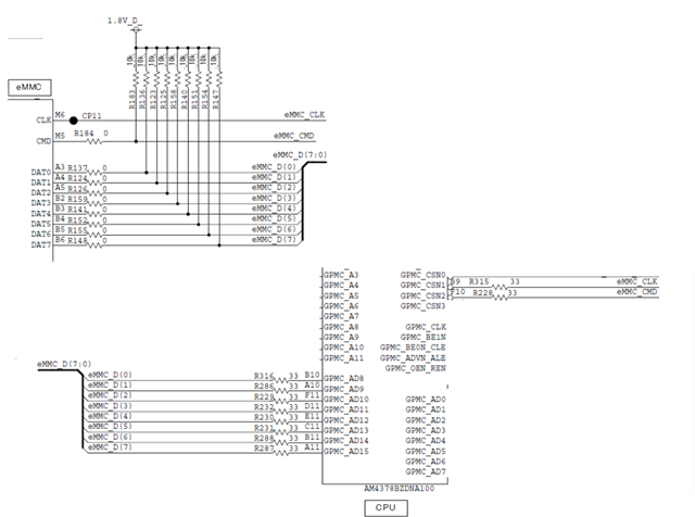
    In this case, my customer is concerned about the intermediate potential
    due to the CPU's internal PD, external 10kΩ PU, and eMMC internal PU
    in eMMC_D(7:0) in the circuit below.


    Could you please answer the additional questions (Q1-Q3).

    I interpreted the previous answers as saying that you recommend
    that the externally connected pull-up resistor (10kΩ) be a smaller value
    during the reset period as well, so that it is above the VIHmin of the CPU,
    regardless of the following provisions mentioned in my first post.

    -CPU internal pull-down resistor (10.58k to 34.61kΩ) 
    -eMMC internal pull-up resistor (10k to 150kΩ *Values stated in JEDEC) 
     
    The requirement for eMMC is described in JEDEC's standard (JESD84-B50)
    in "10.3.4 Bus signal line load" that the external pull-up resistance should be 10k to 100kΩ.

    Q1. Is there any problem to pull down the external pull-up resistor with a lower value
    than that specified by JEDEC?

    Q2. When connecting an eMMC to MMC1 of AM437x, does this mean
    that a resistor of 10kΩ or less (e.g. 1kΩ) is recommended?

    Q3. if you want to avoid deviating from the pull-up resistor range specified by JEDEC,
    "minimize the risk of encountering an unexpected situation where the system cannot boot
    and intermediate levels are applied for a longer period than expected"
    Since it is stated that "the intermediate potential is acceptable for a limited time during the reset period",
    is this acceptable? If so, please let me know the time.

    Please let me know if anything is unclear in the above explanation.
    I deeply appreciate your support.

    Best regards,
    Kanae

  • Shoot-through current will look like a narrow bell-shaped curve when plotted on the y-axis with respect to input voltage on the x-axis, where the current peaks as the input voltage reaches approximately VDD/2. The primary goal needed to reduce long-term reliability risk associated with an intermediate voltage is reducing shoot-through current by getting the input voltage as close as possible to VSS or the respective VDDSHVx power rails.

    The JEDEC eMMC standard only defines internal pulls for DAT[7:1] pins and requires the eMMC deice to turn off these internal pulls once it is configured to transfer data on these pins. So eMMC internal resistors should be off when the device is being used and the system software should have already turned off the internal conflicting pull-down resistors in AM437x. So there should be no concern with intermediate voltage during normal operation. 

    I agree, the signal will have three pulls connected before software is initialized. There is no concern from the JEDEC eMMC standard perspective with this combination of pulls being outside of the 10k to 150K range until communication begins. So you should be able to use a 10K external pull on these signals since the internal pulls will be turned off before communications begins. This will pull the input as high as possible without violating the JEDEC eMMC standard pull-up requirement.  I'm not sure what the input voltage will be while all three resistors are enabled, but hopefully the external 10K pull-up is able to pull the voltage high enough above the VDD/2 potential that shoot-through current is significantly reduced.

    Q1. Is there any problem to pull down the external pull-up resistor with a lower value
    than that specified by JEDEC?

    A1. I'm not sure if I understand this question. Are you asking if the IO can source enough current to pull-down a stronger pull-up? If so, you would need to check the VOL/IOL parameters of the device driving the signal and the VIL requirements of the device receiving the signal to know how much current a IO can sink while still providing a valid input to the other device. 

    Q2. When connecting an eMMC to MMC1 of AM437x, does this mean
    that a resistor of 10kΩ or less (e.g. 1kΩ) is recommended?

    A2. I do not recommend violating the pull requirements defined in an industry standard.

    Q3. if you want to avoid deviating from the pull-up resistor range specified by JEDEC,
    "minimize the risk of encountering an unexpected situation where the system cannot boot
    and intermediate levels are applied for a longer period than expected"
    Since it is stated that "the intermediate potential is acceptable for a limited time during the reset period",
    is this acceptable? If so, please let me know the time.

    A3. As mentioned in A2, I do not recommend violating the pull requirements defined in an industry standard.  We have not define a time limit for an intermediate voltage condition. The customer needs to do the best they can to minimize the time the device is exposed to this condition and get the intermediate voltage as close as possible to VSS or the respective VDDSHVx power rails.

    If the customer doesn't feel comfortable with the risk associated with an intermediate voltage condition, they may need to insert an isolation circuit between the two devices. However, this type of circuit could insert significant delays in the signal paths and cause timing problems for the peripheral. The AM437x device has been in production for several years. There are many similar designs and we have not received any reports related to this concern.

    Regards,
    Paul

  • Hi Paul,

    Thank you for your support.

    I will share it with my customer.

    Best regards,
    Kanae